


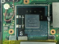
try using 30 awg wire for ground and 3.3v. Actually no. What exactly is your problem? The chip, 1 out of 10 times, doesnt turn on -> power on OFW? Or does it give out error and then power OFW?My picofly installed switch lite boots to ofw sometimes(about 1 out of 10 boots) is this normal behavior?
Last edited by Crung,


 a connector is there on purpose.
