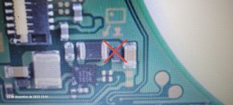
I got a better result when I cut the contact point into triangular shape like in the photo shown. I don't have to worry about the left solder ball as it is not connected anywhere and can be bridge.i have just gotten a bad batch of dat0 adapter now. these chinese seller are tricky one. first i bought 15 they shipped me the good one this time i bought 50 and i got this shitty ones. i will rely on reballing waiting for another batch.
never got loose even once even after stress testing also. You can try.
")