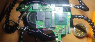
Hacking Hardware Picofly - a HWFLY switch modchip

sadish

Member
Newcomer
Joined
Sep 29, 2019
Messages
14
Trophies
0
Age
23
XP
66
Country
France
It could be you've damaged the hardware during the installation. PicoFly loader does not require DRAM, but hekate does.

You can check that by pressing Vol+ / Vol- on the "No SD" screen - if you get a completely blue image, congratz, you have something broken, DRAM / Power / something else does not work.

Another approach is to run any other payload that does not require DRAM, like ums_loader
yup i tried that and got a blue screen, i got scammed
Post automatically merged:

It could be you've damaged the hardware during the installation. PicoFly loader does not require DRAM, but hekate does.

You can check that by pressing Vol+ / Vol- on the "No SD" screen - if you get a completely blue image, congratz, you have something broken, DRAM / Power / something else does not work.

Another approach is to run any other payload that does not require DRAM, like ums_loader
and how could i run ums_loader if i can't get into a menu on the switch?
 
Last edited by sadish,
  • Sad
Reactions: Takezo-San

Seco_Gobbo2

Member
Newcomer
Joined
Jul 6, 2023
Messages
15
Trophies
0
Age
35
XP
209
Country
Brazil
Hello everybody.
I have a doubt with my rp2040, I passed fw_2.74.uf2 to the chip, proceeded as in the tutorials I saw. However, whenever I connect it back to the PC, the blue led lights up and then blinks yellow, but each time I connect it blinks in a different sequence. This is normal?
Obs. I just plug it into the PC, without holding the boot key.

Sorry for the English, I'm using an online translator

Thank you for your attention
 

roxzii

Well-Known Member
Newcomer
Joined
Nov 11, 2022
Messages
47
Trophies
0
Age
27
XP
248
Country
Portugal
Hi everyone!

I did an install, and at the end the diode values seemed to check out (the CPU pin was a little above 0.900 but my multimeter shows direct probe to probe as anywhere between 20 to 120, so I figured it would be inside the 0.900 range). So picofly works, no sd card screen, all good. After I put in sd card package black screen. Removed sd card, pressed volume+/- to go to OFW, purple screen. Purple screen means I screwed up CMD point. Fixed it.

Now I get a blue screen, so it seems I may have screwed up more than one thing. Everything I found pointed to the APU, so I removed the hwfly flex ribbon, disconnected the pi, still blue screen. I was really careful when installing the flex cable, I knew those caps are heat sensitive so I tried to be as quick as possible, pre-tinned the cable, plenty of flux and everything.

Is it possible I fried one of the two caps and that's the reason for the blue screen? Since the pico manages to glitch shouldn't the caps be fine? I suppose that if there was a problem with those SP1 and SP2 caps the pico would give an error code.

If photos are needed of RST I can post, but since I get to the no sd card screen I'm guessing that shouldn't be the problem. Also don't have photos of the apu with the flex cable since I removed it for testing.

Sorry for the long read, just wanted to explain the problem the best way possible.

Appreciate any help!
 

Attachments

  • finished_noheatsink.jpg
    finished_noheatsink.jpg
    307.4 KB · Views: 28
  • fiished.jpg
    fiished.jpg
    957.4 KB · Views: 29
  • CLK CMD and 3.3V.jpg
    CLK CMD and 3.3V.jpg
    317 KB · Views: 28
  • dat0.jpg
    dat0.jpg
    802.5 KB · Views: 31

cowboy619

Well-Known Member
Member
Joined
Jan 22, 2014
Messages
248
Trophies
1
Age
40
Location
Cape Town, Western Cape
XP
1,810
Country
Hi everyone!

I did an install, and at the end the diode values seemed to check out (the CPU pin was a little above 0.900 but my multimeter shows direct probe to probe as anywhere between 20 to 120, so I figured it would be inside the 0.900 range). So picofly works, no sd card screen, all good. After I put in sd card package black screen. Removed sd card, pressed volume+/- to go to OFW, purple screen. Purple screen means I screwed up CMD point. Fixed it.

Now I get a blue screen, so it seems I may have screwed up more than one thing. Everything I found pointed to the APU, so I removed the hwfly flex ribbon, disconnected the pi, still blue screen. I was really careful when installing the flex cable, I knew those caps are heat sensitive so I tried to be as quick as possible, pre-tinned the cable, plenty of flux and everything.

Is it possible I fried one of the two caps and that's the reason for the blue screen? Since the pico manages to glitch shouldn't the caps be fine? I suppose that if there was a problem with those SP1 and SP2 caps the pico would give an error code.

If photos are needed of RST I can post, but since I get to the no sd card screen I'm guessing that shouldn't be the problem. Also don't have photos of the apu with the flex cable since I removed it for testing.

Sorry for the long read, just wanted to explain the problem the best way possible.

Appreciate any help!
Blue Screen could also be corrupted nand - check your clk point looks like its grounded to the ground point. Dat 0 also looks a bit wonky
 
  • Like
Reactions: roxzii

Dee87

Well-Known Member
Member
Joined
Mar 19, 2023
Messages
1,139
Trophies
1
XP
1,577
Country
Germany
Hello everybody.
I have a doubt with my rp2040, I passed fw_2.74.uf2 to the chip, proceeded as in the tutorials I saw. However, whenever I connect it back to the PC, the blue led lights up and then blinks yellow, but each time I connect it blinks in a different sequence. This is normal?
Obs. I just plug it into the PC, without holding the boot key.

Sorry for the English, I'm using an online translator

Thank you for your attention
That's normal , install 2.73
Since 2.74 has issue with some rp2040
Post automatically merged:

Hi everyone!

I did an install, and at the end the diode values seemed to check out (the CPU pin was a little above 0.900 but my multimeter shows direct probe to probe as anywhere between 20 to 120, so I figured it would be inside the 0.900 range). So picofly works, no sd card screen, all good. After I put in sd card package black screen. Removed sd card, pressed volume+/- to go to OFW, purple screen. Purple screen means I screwed up CMD point. Fixed it.

Now I get a blue screen, so it seems I may have screwed up more than one thing. Everything I found pointed to the APU, so I removed the hwfly flex ribbon, disconnected the pi, still blue screen. I was really careful when installing the flex cable, I knew those caps are heat sensitive so I tried to be as quick as possible, pre-tinned the cable, plenty of flux and everything.

Is it possible I fried one of the two caps and that's the reason for the blue screen? Since the pico manages to glitch shouldn't the caps be fine? I suppose that if there was a problem with those SP1 and SP2 caps the pico would give an error code.

If photos are needed of RST I can post, but since I get to the no sd card screen I'm guessing that shouldn't be the problem. Also don't have photos of the apu with the flex cable since I removed it for testing.

Sorry for the long read, just wanted to explain the problem the best way possible.

Appreciate any help!
Since blue screen and I sat ur using one of those cheap Oat0 adapter I would also say something's wrong with u nand

Also check clk with ground seems to be bridged
 
Last edited by Dee87,
  • Like
Reactions: Seco_Gobbo2

roxzii

Well-Known Member
Newcomer
Joined
Nov 11, 2022
Messages
47
Trophies
0
Age
27
XP
248
Country
Portugal
Blue Screen could also be corrupted nand - check your clk point looks like its grounded to the ground point. Dat 0 also looks a bit wonky
Thanks for the reply!

Yeah, the clk isn't the best of jobs, but i made sure the jacket covers that ground point and have tested several times against ground, getting around mid 0.800's, my multimeter is a bit wonky, direct probe to probe goes anywhere from 20 to 120, so I think it's in the high 0.700's at the pico.

As for dat0 it's a bit crooked because I followed sthetix video and heard it's better to not short with dat1 in these adapters. And I also got the expected readings from the point.

My question is, woulnd't the pico give a led error code in any of these cases? Or would it reach the no sd card screen all the same. I read that if you short the dat0 to dat1 and then turn off the pico without removing the shorting adapter, HOS will write to emmc and corrupt it due to short, giving a blue screen, and I unkowingly did turn off the pico without removing the dat0, but I was already getting blue screen before that when pressing +\- at the no sd screen. But wouldn't the pico give an error code if those 2 points where shorting?

Sorry for the amount of questions, just trying to understand where the problem might be coming from.
 
Last edited by roxzii,

postnutclarity

Member
Newcomer
Joined
Jun 29, 2023
Messages
19
Trophies
0
Age
27
XP
67
Country
United States
2.74 is stable on 95% of rp2040's, so it should (probably) be fine.
So my technician replaced the pcb board with the new one and it looks just as clean as before if not better. The firmware is still 2.74 and it actually glitches inconsistently still. Currently it seems like it will glitch after disconnected the battery for about 6 hours and reconnecting it then turning on the switch. Does this sound like a firmware issue?

Edit: seems like it judging by your reply earlier. Just waiting for it to glitch at some point so I can roll it back to 2.73 with the toolbox 🥲
 
Last edited by postnutclarity,

FreeLander

Well-Known Member
Member
Joined
Apr 6, 2023
Messages
350
Trophies
0
Age
35
XP
467
Country
United States
Hello. I have this interesting observation to share with you guys, can't wait to hear what you think!

Got three OLEDs in today, two glitched fine, but the third gave me *==. Re-wired the whole thing, but no luck. Then I remembered @abal1000x's post where he said this error means the glitching stage hasn't even begun, most likely CLK, which it was.

I re-scratched it, put plenty of solder there, still the same error, BUT GET THIS:
When I removed the CLK wire and turned on the console, nothing happened. I re-wired CLK and BOOM got a good quick glitch. It's like it was reprogrammed after the poor writing after I removed it. Pretty strange.
It works fine now, 400MB, all good.

What do you guys think?


TL;DR:
Got *==, re-worked CLK but still got the error. It was fixed when I turned on the console with CLK removed and then re-resoldered.
 
  • Like
Reactions: Takezo-San

Takezo-San

Well-Known Member
Member
Joined
May 3, 2023
Messages
261
Trophies
0
Age
39
XP
348
Country
Seychelles
I bought both the stencils and curious how you use it with the solder balls? Any tips?
BTW, I tried with the magnetic jig and stencil with paste and it came out perfectly first try. I struggled so many times using paste and holding down the stencil with tweezers never worked.
Now I can mod my oled :)
Get In!!!
Post automatically merged:

If it is facedown then cannot install without cutting shield bridge. But if somehow you can isolate some part of mosfet Drain with kapton then you can do without cutting shield.
For pulldown resistor even with 10K sometime(sometime) it will give longer glitch or even failed. So i leave it for now, until i can find higher r value.
Go with this one if you can. The best so far.
View attachment 379931
Post automatically merged:


Wow .. nice job.. will try to move the led to this also.. but i dont know if i want to diaseemmble the whole board just to install the led, considering all those flexs and connectors.
Btw where is the original home button led?
Got this one and its huge. Like twice the size of the IRF8736PbF. The whole point was too find something that doesn't require the metal bridge cut...
Post automatically merged:

Can anyone confirm for me if number 6 (on the diagram) is the voltage regulator? That isn't really required for this mod and can be removed because @impeeza wrote a while ago 'that regulator is for convert the 5V of the USB to 3.3V and you can get 3.3V directly from console board.' Is it safe to do so?

RP2040-Zero-Pico-like-MCU-wersja-mini-Producent-WaveShare.png

Thank you in advance.
Post automatically merged:

this one looks like a mesh fabric, what that used for!?
 
Last edited by Takezo-San,

cgtchy0412

Well-Known Member
Member
Joined
Apr 26, 2023
Messages
287
Trophies
0
Age
41
XP
432
Country
Indonesia
Any luck?
Ive redone the instalation.
It seems this is software issue, but still im not sure.
You can try to replace the sdcard and also just install barebone hekate and also default atmosphere at least it minimize the issues.
Of course this not happen on other unit, not tried to replace the rp board yet. Maybe ill try to flash older firmware 2.6.4 later and see what happen
Post automatically merged:

I use 30awg, it's a good ?
Please dont.
I have #30 and #36 AWG by hand , I can tell you #30 is dangerous yet soldering on components but when trying to sort out all wires with just little pull/lift.
Yup a few times it gave me sleepless night.
 
Last edited by cgtchy0412,

lightninjay

Well-Known Member
Member
Joined
Mar 28, 2023
Messages
560
Trophies
0
Age
31
XP
1,373
Country
United States
Can anyone confirm for me if number 6 (on the diagram) is the voltage regulator? That isn't really required for this mod and can be removed because @impeeza wrote a while ago 'that regulator is for convert the 5V of the USB to 3.3V and you can get 3.3V directly from console board.' Is it safe to do so?

View attachment 382128
Thank you in advance.
Yes, you can remove the LDO (Low DropOut Voltage Regulator) after flashing the firmware through USB. Once you remove it though, it becomes more difficult to flash over USB.
 

roxzii

Well-Known Member
Newcomer
Joined
Nov 11, 2022
Messages
47
Trophies
0
Age
27
XP
248
Country
Portugal
Hi everyone!

I did an install, and at the end the diode values seemed to check out (the CPU pin was a little above 0.900 but my multimeter shows direct probe to probe as anywhere between 20 to 120, so I figured it would be inside the 0.900 range). So picofly works, no sd card screen, all good. After I put in sd card package black screen. Removed sd card, pressed volume+/- to go to OFW, purple screen. Purple screen means I screwed up CMD point. Fixed it.

Now I get a blue screen, so it seems I may have screwed up more than one thing. Everything I found pointed to the APU, so I removed the hwfly flex ribbon, disconnected the pi, still blue screen. I was really careful when installing the flex cable, I knew those caps are heat sensitive so I tried to be as quick as possible, pre-tinned the cable, plenty of flux and everything.

Is it possible I fried one of the two caps and that's the reason for the blue screen? Since the pico manages to glitch shouldn't the caps be fine? I suppose that if there was a problem with those SP1 and SP2 caps the pico would give an error code.

If photos are needed of RST I can post, but since I get to the no sd card screen I'm guessing that shouldn't be the problem. Also don't have photos of the apu with the flex cable since I removed it for testing.

Sorry for the long read, just wanted to explain the problem the best way possible.

Appreciate any help!
Update: Resoldered the flex cable, turned the pi back on. Tried running UMS-Loader as a payload and it ran. Not sure what to make of this. Since it only uses RAM and it works, the problem must be in the APU?

Would appreciate any help, really lost on this one.
 

abal1000x

Well-Known Member
Member
Joined
Jun 5, 2022
Messages
1,062
Trophies
0
XP
1,367
Country
Gaza Strip
Update: Resoldered the flex cable, turned the pi back on. Tried running UMS-Loader as a payload and it ran. Not sure what to make of this. Since it only uses RAM and it works, the problem must be in the APU?

Would appreciate any help, really lost on this one.
ums-loader only uses nvidia's iram so the cpu is okay. i might check the connection between apu and dram the next of it. Theres lot of small trace which might broken because of mod activity.
 
  • Like
Reactions: roxzii

roxzii

Well-Known Member
Newcomer
Joined
Nov 11, 2022
Messages
47
Trophies
0
Age
27
XP
248
Country
Portugal
I can confirm that, this Oled only shows picofly logo, with micro sd black screen and vol+- blue screen and without picofly same blue screen, MAX77812 IC is shorted, waiting for replacement
Thanks so much for the reply! Okay, going to test that! Any specific caps around the IC I should check for shorts?
Post automatically merged:

ums-loader only uses nvidia's iram so the cpu is okay. i might check the connection between apu and dram the next of it. Theres lot of small trace which might broken because of mod activity.
Thanks for the reply! I haven't messed around too much around there. Could a tiny spec of thermal paste do anything like this? I noticed that when I cleaned the APU with IPA some tiny pieces of thermal paste went under the metal shielding and near the ram chips, I tried cleaning as best as I could, but maybe some tiny spec ended up in the wrong place? In the photo I've attached there can be seen tiny specs of thermal paste between traces. Anyway, I'm going to check those traces right away, thank you!
 

Attachments

  • CLK CMD and 3.3V.jpg
    CLK CMD and 3.3V.jpg
    317 KB · Views: 35
Last edited by roxzii,
  • Like
Reactions: malgamer

Site & Scene News

Popular threads in this forum

General chit-chat
Help Users
    Psionic Roshambo @ Psionic Roshambo: Taylor Swift death metal AI cover please lol