Hacking Hardware Help with HWFLY and OLED

Phantomas77

Well-Known Member
OP
Member
Joined
Dec 19, 2022
Messages
284
Trophies
0
XP
720
Country
Italy
Hey guys,
Have been strugling with HWFLY and brand new OLED switch for about a week without getting the chip to work.
Quick background: I did lots of PS2 modchip installs back in the day and lately have been comfortable soldering 0402 SMDs, though I'm new to hot air rework.

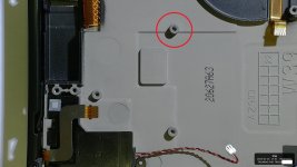
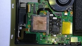
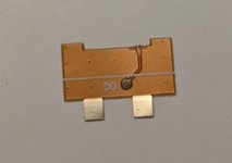
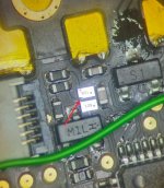
Bought what seems to be an HWFLY 4.1 (Lite chip with OLED cables) from Ali. I followed STHETIX scheme and only used the CPU flex and DAT0 adapter, the rest was wired with enamel wire and AWG30 for GND, 3.3V and RST. The install pics are attached.

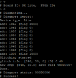
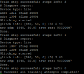
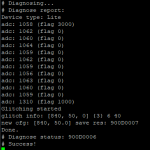
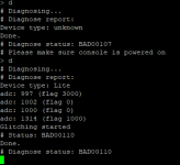
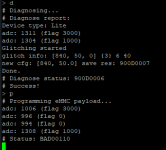
I flashed it with HWFLY-NX 0.71 and when I turn the Switch ON, I get what seems a yellow (Red+Green) blinking light, followed by green light but the console boots to OFW. With ChipNX 0.32 FW blinks what seems a white light endlessly and the screen is black.

The diode readings are as follow:

Code:
Pin            + on GND         -  on GND
Dat0        0.427                    0.750
CMD         0.458                    0.750
CLK            0.427                    0.751
RST            0.403                    OPEN

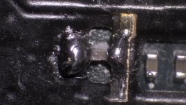
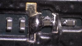
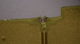
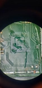
I tried a couple of times reflowing the eMMC, since I was getting the same readings above but the adaptor flex was moving. Today I repeated it with different type liquid type of flux and a slightly larger nozzle for the hot air station, following this profile: 1min@160 C + 1min@250 C + 1min@360 C. I pushed the flex even more under the eMMC, where the white line on the flex is not seen anymore (since on the pics above it was still showing). I did not tried to move the flex again, since the readings are always the same. I resoldered again the CMD and CLK points, reflashed the chip, but the results are the same: with HWFLY-NX 0.71 it lights green and boots to OFW, while with ChipNX infinetely blinks white.

Yes, it is my first switch install, though I followed stricly the STHETIX scheme and did my research before doing this job, though this is getting really frustrating and I would like to ask for your help.

Questions: i) did the same thing happened to anyone? ii) can I get a stable diode readings and still have problems with Dat0 connection, but shouldn't I be getting a red light?

Any advice will be much appreciated,
Thanks!
 

Attachments

  • img_20221215_200532.bmp
    5.9 MB · Views: 154
  • img_20221215_200550.bmp
    5.9 MB · Views: 109
  • img_20221215_200611.bmp
    5.9 MB · Views: 135
  • img_20221215_200642.bmp
    5.9 MB · Views: 134

randy_w

Well-Known Member
Member
Joined
Feb 27, 2021
Messages
709
Trophies
0
Age
34
XP
1,374
Country
United States
HWFLY 4.1
First off, I don't trust those v4.1/v5 chips with BGA FPGA.

If you are on original chipnx firmware, white light means RST/CMD/CLK is not connected properly and red light means DAT0 is not connected properly. Now all your readings look good (black on ground), so I guess it's not a soldering problem. It's normal that RST shows as open on some multimeters.

Does the chip finish training when it's flashed with hwfly-nx firmware? Do you see the purple light at all or it goes straight to green light and boots ofw? Sounds like something's wrong with your modchip, I'd say connect the chip to your pc and see if it gives any error code over serial port.
 

Phantomas77

Well-Known Member
OP
Member
Joined
Dec 19, 2022
Messages
284
Trophies
0
XP
720
Country
Italy
Does the chip finish training when it's flashed with hwfly-nx firmware? Do you see the purple light at all or it goes straight to green light and boots ofw? Sounds like something's wrong with your modchip, I'd say connect the chip to your pc and see if it gives any error code over serial port.
I see a blinking yellow light for like 15s on the first boot after flashing the hwfly-nx 0.71 FW, than it goes to green while the console boots to OFW. On the second boot, it jumps right away to the green light and OFW. I've never seen the purple light though. Could the absense of purple light suggest that I have soldering/connection issue?

Later I'll do the debug console dump to check the logs. I flashed the chip with hwfly-nx 0.71 FW before install, so never tested it with the original that it came (I still have the original backup when I flashed the hwfly-nx). Have been reading on the forum that some chips, I assume mainly these with BGA FPGA work only with "original" and 0.31 FW, which I'll try to flash it later as well. Should have went with v4 chip probably...

Thanks for your help randy_w!
Post automatically merged:

Connected it through PuTTY and got this output for diagnose ("d"), than new training ("t") and diagnose ("d"). What do you think of it? And what is the command to check if the connection to eMCC is good?

Thanks!
 

Attachments

  • Screenshot_9.png
    Screenshot_9.png
    10.1 KB · Views: 203
  • Screenshot_8.png
    Screenshot_8.png
    13.8 KB · Views: 130
  • Screenshot_7.png
    Screenshot_7.png
    10.9 KB · Views: 150
Last edited by Phantomas77,

randy_w

Well-Known Member
Member
Joined
Feb 27, 2021
Messages
709
Trophies
0
Age
34
XP
1,374
Country
United States
That's really weird, because the debug console doesn't even give any error message and the chip thinks the glitching completes without any error.

Your emmc clk/cmd/dat0 readings are good, if they are not connected properly they will show as open circuit. Don't push the emmc adapter in too much once solder is melted, you could easily mess up the BGA and have to do a reball..

At this point I'm pretty sure the chip is faulty, your soc ribbon cable soldering seems very solid and all emmc points have good readings. Maybe ask your seller for a factory firmware, if it doesn't work then ask for a refund.
 
  • Like
Reactions: Phantomas77

swutch

Well-Known Member
Member
Joined
Apr 16, 2019
Messages
219
Trophies
0
XP
1,534
Country
Austria
Your readings looks ok.

You could try this special 0.31 Firmware.
Its the only firmware where my v5 BGA FPGA can finish training mode.
 
  • Like
Reactions: Phantomas77

Phantomas77

Well-Known Member
OP
Member
Joined
Dec 19, 2022
Messages
284
Trophies
0
XP
720
Country
Italy
Think I made a little progress on diagnosing this. First of all, thank you both for your support.

I flashed the "special v0.31" firmware from swutch, and somehow it "feels" like the right one for this chip, since with debug console I was able to reset the chip ("r" command), than run diagnostic ("d") and finally I was able to see the purple light for 10 seconds or so, but then it gave me a BAD00110 error and the LED on the chip was RED. Same thing happened if I try to erase or program ("e" and "p" commands) the eMMC, both in "0.31 special" and "hwfly-nx 0.71" firmwares. Please see the attached printscreens.

So it seems that the chip cannot communicate with eMMC and I still need to work on my soldering, mainly on DAT0, CLK and CMD points, right? I think that I will start to reflow, by the 4th time, the eMMC. I went with max temp of 360 degrees Celcius for 1min, but will try to push it to 380 or 400, hoping that it will survive.

Do you have any other suggestions of where to look?

Thanks again!
 

Attachments

  • 0.31special.png
    0.31special.png
    10.2 KB · Views: 156
  • hwfly-nx0.71.png
    hwfly-nx0.71.png
    10.9 KB · Views: 152

swutch

Well-Known Member
Member
Joined
Apr 16, 2019
Messages
219
Trophies
0
XP
1,534
Country
Austria
I wouldn't go to high, it can kill your eMMC.
On my Switch I had to remove the corner of the Dat0 adapter to make it fit because there is a component next to my Samsung eMMC.
Dat0_switch.jpg


edit:
and don't push it to far ;-)
Does your switch still boot when the chip is unplugged?
 
Last edited by swutch,
  • Like
Reactions: Phantomas77

Phantomas77

Well-Known Member
OP
Member
Joined
Dec 19, 2022
Messages
284
Trophies
0
XP
720
Country
Italy
Mine Dat0 adapter is slighly different from yours, it has only the horizontal white line. But since I have the same Samsung eMMC, will cut the angle as you did, thanks for the suggestion.

With your 0.31v firmware I get black screen, but with hwfly-nx I get green light on the modchip and it boots directly to OFW. Tomorrow I should get my hands on a very thin AWG42 wire for reworking the CMD and CLK points, will keep you updated 😉
 

Attachments

  • PXL_20221214_180427118.MP__01.jpg
    PXL_20221214_180427118.MP__01.jpg
    57.3 KB · Views: 151
  • Like
Reactions: swutch

swutch

Well-Known Member
Member
Joined
Apr 16, 2019
Messages
219
Trophies
0
XP
1,534
Country
Austria
Then your adapter should fit, mine was 1-2 mm too wide.
With my Samsung eMMC I get a value of ~0.6v when it is in the right position.

Black to ground:
3v3 0.812v
C 0.605
A 0.825
D 0.826
B OL

Red to ground:

3v3 0.453
C 0.472
A 0.474
D 0.473
B 0.442

C differs from my other Points
 
  • Like
Reactions: Phantomas77

Phantomas77

Well-Known Member
OP
Member
Joined
Dec 19, 2022
Messages
284
Trophies
0
XP
720
Country
Italy
Well, FML...

I resoldered the CMD and CLK points, but the BAD00110 error was still present. SO I went to check on the DAT0 adapter, it seemed a fixed but I wasn't sure about it since there was a lot of flux. After desoldering the anchors, I lost the diode reading so I thought of pulling it out. The pic in the attachment is self explanatory.... Probably it happened when I pushed it too far or when I tried to remove it today and it was fixed to the eMMC. Though I'm really glad that the Switch boots to OFW!! Now I need to find someone to perform a reball... I only have the hot air station, no eMMC stencil nor practice to do it on my own, so I think I'll trust a professional for that. Or is it a "doable" task and I should invest in the materials to perform it?

If by the end it comes out that the modchip is defective as you already suspected, it will be a very sad moment...

Thank you all, will keep you updated!
 

Attachments

  • DAT0.jpg
    DAT0.jpg
    1.1 MB · Views: 151

swutch

Well-Known Member
Member
Joined
Apr 16, 2019
Messages
219
Trophies
0
XP
1,534
Country
Austria
Well, FML...

I resoldered the CMD and CLK points, but the BAD00110 error was still present. SO I went to check on the DAT0 adapter, it seemed a fixed but I wasn't sure about it since there was a lot of flux. After desoldering the anchors, I lost the diode reading so I thought of pulling it out. The pic in the attachment is self explanatory.... Probably it happened when I pushed it too far or when I tried to remove it today and it was fixed to the eMMC. Though I'm really glad that the Switch boots to OFW!! Now I need to find someone to perform a reball... I only have the hot air station, no eMMC stencil nor practice to do it on my own, so I think I'll trust a professional for that. Or is it a "doable" task and I should invest in the materials to perform it?

If by the end it comes out that the modchip is defective as you already suspected, it will be a very sad moment...

Thank you all, will keep you updated!
Looks like the adapter was pushed in too far, with temperatures too high. Luckily your OFW still boots.
If the solder ball is not glued with plastic you might not need a reball.

I would recommend low melt solder for soldering an new Dat0 adapter. E.g.:

https://de.aliexpress.com/item/1005...t_main.57.79585c5fZ2E5eX&gatewayAdapt=glo2deu

260C is enough with this.
 
  • Like
Reactions: Phantomas77

Phantomas77

Well-Known Member
OP
Member
Joined
Dec 19, 2022
Messages
284
Trophies
0
XP
720
Country
Italy
So I contacted a professional with the right tools and skills and reballing was done with Dat0 jump-wire connection. When the eMMC was unsoldered, I checked the continuity for the CLK wire between the chip and the bottom of the eMMC, so my previous soldering was fine.

So after the assembly I measured the diode values, and they're the same as before, even for the Dat0.
After resetting the chip and letting it try to glitch, BAD00110 error is still there, and the console boots to OFW. Tried again different FWs, but the same error persists.

One thing I noticed was a broken angle of what seems a crystal on the HWfly modchip, check the pic below. Does anyone have more info about that component?

I don't know what is causing this failure, but this is getting very frustraiting... I already contacted the seller, which sent me the original firmware, but no luck, so now I'm looking to resolve this somehow, maybe ask for a new chip. Basically, no Switch fun during Christmas holidays.

Any other ideas where I should look?

Thank you all for the support!
 

Attachments

  • IMG-20221223-WA0003.jpg
    IMG-20221223-WA0003.jpg
    122 KB · Views: 127
  • IMG-20221223-WA0002__01.jpg
    IMG-20221223-WA0002__01.jpg
    160.4 KB · Views: 140
Last edited by Phantomas77,

Phantomas77

Well-Known Member
OP
Member
Joined
Dec 19, 2022
Messages
284
Trophies
0
XP
720
Country
Italy
What are your diode values for sp1 and sp2? They don’t look flush
Hi! I checked the values:
Code:
//Diode mode on HWFly chip
Pin                + on GND            - on GND

CPU I            0.424                0.521
CPU II            0.27                0.20

//Diode mode (- on GND) or resistance measurements on terminals of flex soldered to caps on CPU read similar values:

   SP1                    SP2
0    17.9 Ohm        18.3 Ohm    0

I resoldered the SP1 and SP2 contacts, the reading did not change. I remeasured all the values on chip in diode mode, here they're:
Code:
//Diode mode on HWFly chip
Pin                + on GND            - on GND

DAT0            0.437                0.881
CMD                0.471                0.874
CLK                0.439                0.881
RST                0.405                OPEN
CPU I            0.422                0.522
CPU II            0.24                0.18
+3.3 V            0.445                0.853

I tried different FWs that I found on the forum, sthetix, hwfly-nx and original from Ali that the seller sent, some of them successfully train, but when I perform "Diagnose" through SSH, they give BAD00110 and a red light (report in attachment).

It still looks life the chip cannot write to the eMMC for some reason, though I don't know where to look for fixing this. I'm in contact with the seller, but he does not seem very cooperative after I asked for a refund.

@cowboy619 do the CPU values look OK to you?

Thanks!
 

Attachments

  • summary.pdf
    118.6 KB · Views: 150

kylum

Well-Known Member
Member
Joined
Dec 8, 2008
Messages
394
Trophies
1
XP
1,483
Country
United States
Did you flash the chip before installing/ first boot or training? Also, did you flash both bootloader and firmware? I ask this because My personal Oled chip refuses to work with any bootloader other than what I shipped with which is different than what you can find out in the net. This includes what the “reseller” will provide, well in my case.

I updated my bootloader and firmware. Chip was previously working! After doing so it started exhibiting same behaviors as yours. Reflashing with multiple different bootloaders and firmware resulted in different behaviors. Fortunately, Mena had a one to one backups of multiple different chips and one of them got me back up and running.

Also, I would inspect the Hwfly chip as I have also had one I installed for a neighbor have some bridging on the board causing it to not work properly. After clearing the bridge it worked. This of course my be a one off but also tells me the QC from the manufacture and the resellers are less than adequate. Though, I have not done a crap ton of install either.
 

Phantomas77

Well-Known Member
OP
Member
Joined
Dec 19, 2022
Messages
284
Trophies
0
XP
720
Country
Italy
Yep, unfortunately I flashed it with hwfly-nx 0.7.1 before install, both bootloader and FW. These v4.1 seem really sketchy with the FW, and I didn't know about the bootloader, though I tried different versions as reported in the file. I even tried the one that the reseller sent, and there was as well a "config" file, but since I didn't have the .bat file, I couldn't flash it. Soon I should have access to some "reseller" FWs, will post them here.

I'm glad that you got your running! Can you share by any chance the files that made it work? So were you getting as well the BAD00110 error? I won't be able to test it since I sent back the chip, but maybe it could be helpful for others.

Next week I should receive a V4 (QFN FPGA) as a replacement for the v4.1 (and got a V5 as a backup, since you never know with these chips) with what it seems an original TX IC, at least this is what they say, since I could do as well a beautiful "SxT" laser incision on the IC quite easily :rofl2: Will test both chips on the OLED and can try different FW in case it starts working.

Since I left the V4.1 CPU ribbon cable attached, do you think its the same pinout as for V4 and V5? If so, it will save a lot of time while testing the both chips.

Another thing, after mounting and dismounting more than dozen times the heatsink, it seems that the thread on one of the supports where the screw gets inserter got damaged. What my option would be here? The switch is brand new and I would not like to replace the whole back casing...

Thank you all for help, hope to provide some answers soon!
 
  • Like
Reactions: swutch

kylum

Well-Known Member
Member
Joined
Dec 8, 2008
Messages
394
Trophies
1
XP
1,483
Country
United States
I will try and find the full firmware merged with bootloader when I get home for the one that finally worked for me. If I saved it as I had to wipe my computer a few months back. However, I previously sent this attached bootloader only file to someone else so had it on my phone so here you go!

Havent done an install in months or with the v5 but pin out should be the same since the boards are the same and only the ribbons are the difference( I believe so any way) someone can correct me if I’m wrong.

What kind of damage got pics?

Update: So I wanted to update to the latest FW and needed to also update the Hwfly before updating. The update failed through Hwfly-tool box. So I had to tare down to update via USB. To make sure the bootloader I posted here was indeed the one I thought it was which it is. I flashed the full Hwfly-nx firmware and bootloader to what I thought would have bricked it like previously. Well to my surprise it actually worked and the bootloader has been updated. Still leaving this bootloader here in case it helps others in the future because it was the only one that would unbrick my Hwfly previously
 

Attachments

  • Bootloader.zip
    7.9 KB · Views: 78
Last edited by kylum,
  • Like
Reactions: Phantomas77

Phantomas77

Well-Known Member
OP
Member
Joined
Dec 19, 2022
Messages
284
Trophies
0
XP
720
Country
Italy
Hey guys, finally we have a closure...

After receiving V4 and V5 few days ago, today I managed to test them. But before, I had to remove the OLED CPU ribbon (since it has flipped contacts on the chip side connection), and it wasn't much fun to play with, even after applying a good amount of flux, check the pics and you can see that it looks like I moved the SP2 cap, but thankfully everything stayed connected. Soldered right away the V5 CPU flex, which has much better fit than V4. I used the chips' stock FW, and both V4 and V5 glitched quickly into HEKATE screen. I wrapped the install with V5 chip and 0.7.2 hwfly-nx FW that worked perfectly.

So, here're some take-away points for someone who gets shipped by google to this topic regarding BAD00110 error:
  • if your readings are correct, listen to @randy_w whose advice was right from the beginning: probably it is the chip and/or CPU flex problem.
  • before reporting the issue, consider checking the FW and bootloader sent by swutch and kylum.
  • contact right away the seller and ask for the replacement chip: I had to ship mine back to China, but in parallel they sent me another one (asked for the V4).
  • here's another link that could be useful: FW repo from Ali
@kylum glad that the bootloader worked! Regarding the heatsink problem, I was referring to the screw hole in the pic (red circle), but I used longer screws and it seems to hold it quite well.

Special thanks to @swutch for the continuos support and to all of you for your help.

Cheers!
 

Attachments

  • heatsink_support.jpg
    heatsink_support.jpg
    380.6 KB · Views: 152
  • HWFLY V5.jpg
    HWFLY V5.jpg
    655 KB · Views: 146
  • SP1.jpg
    SP1.jpg
    336.5 KB · Views: 140
  • SP2.jpg
    SP2.jpg
    319.5 KB · Views: 169

Site & Scene News

Popular threads in this forum

General chit-chat
Help Users
    Psionic Roshambo @ Psionic Roshambo: By the power of Florida Man, I have the power!!! *Lifts up meth pipe* Meth Man!!! lol