Hardware Xbox One X - BGA piece NFD740, please help me to find it !

FXDX

Well-Known Member
OP
Member
Joined
Sep 15, 2019
Messages
325
Trophies
0
XP
1,991
Country
Dominican Republic
Hello.
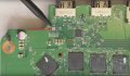
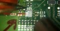
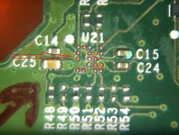
I'm looking for this piece for Xbox one X. I think that NFD740 is a mosfet. I can't find it anywhere. Does anyone know if the id code is correct or should I look for it under another ID number? Thank for the help and apologies for my bad English.
 

Attachments

  • 22.jpg
    22.jpg
    296.2 KB · Views: 992
  • 11.jpg
    11.jpg
    270 KB · Views: 949
  • xbox X.jpg
    xbox X.jpg
    168.1 KB · Views: 985

testerfan

Well-Known Member
Member
Joined
May 28, 2013
Messages
179
Trophies
1
Age
44
Website
www.fixxmaster.com
XP
2,240
Country
United States
it's not a MOSFET, it's an ESD Protection and Signal Booster for HDMI Source IC, made by STMicroelectronics, and 740 is just a production date code (2017, week 40), the NF is a correct marking for the IC (D is for manufacturing location), but you can't buy it, because STMicroelectronics hasn't released it to the public yet (there is no datasheet for it), so at this moment you can only get it from a donor board
 

FXDX

Well-Known Member
OP
Member
Joined
Sep 15, 2019
Messages
325
Trophies
0
XP
1,991
Country
Dominican Republic
it's not a MOSFET, it's an ESD Protection and Signal Booster for HDMI Source IC, made by STMicroelectronics, and 740 is just a production date code (2017, week 40), the NF is a correct marking for the IC (D is for manufacturing location), but you can't buy it, because STMicroelectronics hasn't released it to the public yet (there is no datasheet for it), so at this moment you can only get it from a donor board
Thank you very much Sir, for information.
 
Last edited by FXDX,
  • Like
Reactions: MaikAmsterdam

RealCyborg

Member
Newcomer
Joined
Apr 26, 2020
Messages
7
Trophies
0
XP
52
Country
Germany
I have a board with missing U21 here as well ... is there any way to replace it other than to get it from a donor board (which itself is quite hard to find)?
 
  • Like
Reactions: FXDX

iamxquisite

New Member
Newbie
Joined
Dec 16, 2020
Messages
1
Trophies
0
Age
34
XP
43
Country
United States
I think I'm having the same problem I have replaced the Retimer IC and HDMI port and still getting no signal when I power on the Xbox One X.
 
  • Like
Reactions: FXDX

EMF2

New Member
Newbie
Joined
Aug 22, 2021
Messages
1
Trophies
0
Age
32
XP
34
Country
Paraguay
Hola investigando un poco, creo que puedes usar la xbox one x sin la u21 haciendo una serie de puentes, podrías verificar este proceso por favor, no puedo enviar el enlace del video pero puedes buscarlo como xbox one x u21, un video de un polaco que une los pines del u21

--------------------- MERGED ---------------------------

Hello, researching a bit, I think you can use the xbox one x without the u21 by making a series of bridges, you could verify this process please, I can not send the link of the video but you can look for it as xbox one x u21, a video of a Polish that bridges the pins of the u21
 
  • Like
Reactions: FXDX

jkyoho

Well-Known Member
Member
Joined
Sep 2, 2020
Messages
1,269
Trophies
0
Age
39
Location
TORONTO
Website
form.jotform.com
XP
2,198
Country
Canada
is this IC pin A3 (c14 cap right side) goes ground? I have a XSX came in today have HDMI PORT repaired but still no image

NVM, I saw a video making jumper to bypass u21. Anyone can comfirm the jumper?
 
Last edited by jkyoho,
  • Like
Reactions: FXDX

CurbCake

Member
Newcomer
Joined
May 2, 2018
Messages
8
Trophies
0
Age
26
XP
64
Country
United States
I had my IC retimer go out, so I replaced it and it worked for about a week of watching disney+. One day, the video went out again. I replaced the ic retimer again and still no display. I started to look at other chips around and came across this thread. I managed to successfully do the u21 bypass and the video instantly worked again, even with the first IC retimer chip I used on the first replacement. Games work fine but Disney+ will not play anything. It gives error 39 every time. Does this have something to do with having to use manual and select hdmi in the settings? Is there really no other way around this or a way to get a new chip without a donor board ?
 
  • Like
Reactions: FXDX

testerfan

Well-Known Member
Member
Joined
May 28, 2013
Messages
179
Trophies
1
Age
44
Website
www.fixxmaster.com
XP
2,240
Country
United States
I had my IC retimer go out, so I replaced it and it worked for about a week of watching disney+. One day, the video went out again. I replaced the ic retimer again and still no display. I started to look at other chips around and came across this thread. I managed to successfully do the u21 bypass and the video instantly worked again, even with the first IC retimer chip I used on the first replacement. Games work fine but Disney+ will not play anything. It gives error 39 every time. Does this have something to do with having to use manual and select hdmi in the settings? Is there really no other way around this or a way to get a new chip without a donor board ?
you can get a QFN version of this chip, which is available: HDMI2C1-6C1. You'll need adapter board to place the QFN chip, and then run link wires from the adapter board to the appropriate points on the motherboard
 
  • Like
Reactions: CurbCake

CurbCake

Member
Newcomer
Joined
May 2, 2018
Messages
8
Trophies
0
Age
26
XP
64
Country
United States
you can get a QFN version of this chip, which is available: HDMI2C1-6C1. You'll need adapter board to place the QFN chip, and then run link wires from the adapter board to the appropriate points on the motherboard
Are there already made adapter boards that you know of ?
 

testerfan

Well-Known Member
Member
Joined
May 28, 2013
Messages
179
Trophies
1
Age
44
Website
www.fixxmaster.com
XP
2,240
Country
United States
Are there already made adapter boards that you know of ?
because it's not a standard QFN chip (with the same number of pins on each side), and it has 5-4-5-4 pins combination, there are no exact adapter boards for it. What i would get is a QFN-20 board (with 0.5mm pitch), something like this: qfn20 0.5mm adapter board and then offset the chip from the center when reflowing it on the adapter board, so that the side with 4 pins aligns with the pads (some modification might be required to one of the sides with 5 pins, like cutting the ground plate copper from the board and extending the pads)
 

CurbCake

Member
Newcomer
Joined
May 2, 2018
Messages
8
Trophies
0
Age
26
XP
64
Country
United States
because it's not a standard QFN chip (with the same number of pins on each side), and it has 5-4-5-4 pins combination, there are no exact adapter boards for it. What i would get is a QFN-20 board (with 0.5mm pitch), something like this: qfn20 0.5mm adapter board and then offset the chip from the center when reflowing it on the adapter board, so that the side with 4 pins aligns with the pads (some modification might be required to one of the sides with 5 pins, like cutting the ground plate copper from the board and extending the pads)
You are right about no boards being available. I grabbed this QFN-18 to DIP-22 SMT Adapter yesterday and 4 HDMI2C1-6C1 chips for practice. Once I figure out the right pinout I will try and use something that is smaller like you linked.
 

testerfan

Well-Known Member
Member
Joined
May 28, 2013
Messages
179
Trophies
1
Age
44
Website
www.fixxmaster.com
XP
2,240
Country
United States
You are right about no boards being available. I grabbed this QFN-18 to DIP-22 SMT Adapter yesterday and 4 HDMI2C1-6C1 chips for practice. Once I figure out the right pinout I will try and use something that is smaller like you linked.
that board should work, just desolder the DIP socket pins from the other side and it should be good to go. It's slightly big in dimensions (ideally you would want something like 15x15mm to fit it in nicely on the empty space of the motherboard), as it will be hard to position it closely to the port, because of the heatsink and other components and you would have to run long wires from somewhere farther out, but it should be fine for initial test.
And i'll see if i can help with the pinout for the chip once the holiday rush is over and i have some free time
 
  • Like
Reactions: CurbCake

CurbCake

Member
Newcomer
Joined
May 2, 2018
Messages
8
Trophies
0
Age
26
XP
64
Country
United States
that board should work, just desolder the DIP socket pins from the other side and it should be good to go. It's slightly big in dimensions (ideally you would want something like 15x15mm to fit it in nicely on the empty space of the motherboard), as it will be hard to position it closely to the port, because of the heatsink and other components and you would have to run long wires from somewhere farther out, but it should be fine for initial test.
And i'll see if i can help with the pinout for the chip once the holiday rush is over and i have some free time
I just got home from vacation yesterday and just got it soldered on the test board now. Next onto figuring out the pinout.
IMG_0263.jpg
 
Last edited by CurbCake,

Site & Scene News

Popular threads in this forum

General chit-chat
Help Users
    Xdqwerty @ Xdqwerty: aeiou