

You are using an out of date browser. It may not display this or other websites correctly.
You should upgrade or use an alternative browser.
You should upgrade or use an alternative browser.


below is the correct pinout for the chip, updated on 05/16/22I just got home from vacation yesterday and just got it soldered on the test board now. Next onto figuring out the pinout.

Last edited by testerfan,
also, a bit of advice on wiring: secure the adapter board to the motherboard first, you don't want it dangling in the air with wires, that's a sure way to pull the pads off the board. Run wires (use 0.10mm enameled wire, if similar thickness insulated wire not available) to the end cap of the surrounding components where possible (which are almost all of them, except for B5) and directly to the pins of the port (for Pin 19 only), for Pin 13 run the wire to the top side of the R10 resistor (find it between two HDMI ports), and you can wire VDD_IC and VDD_5V directly to the test points if needed as well (find them under the power supply, C3 - to TP10/V_3P3STBY and C4 - to TP11/V_5P0)
When you say "Pin", are you referring to the pin numbers on the adapter board or the Datasheet for the HDMI2C1-6C1? I guess they are the same huh ?also, a bit of advice on wiring: secure the adapter board to the motherboard first, you don't want it dangling in the air with wires, that's a sure way to pull the pads off the board. Run wires (use 0.10mm enameled wire, if similar thickness insulated wire not available) to the end cap of the surrounding components where possible (which are almost all of them, except for B5) and directly to the pins of the port (for Pin 19 only), for Pin 13 run the wire to the top side of the R10 resistor (find it between two HDMI ports), and you can wire VDD_IC and VDD_5V directly to the test points if needed as well (find them under the power supply, C3 - to TP10/V_3P3STBY and C4 - to TP11/V_5P0)
*edit Oh wow, you mean the HDMI port... Glad I was already doing that xD
*edit2 With TP10/V_3P3STBY and TP11/V_5P0, there are two points then a little point to the left of it. Which one did you mean ?
Last edited by CurbCake,
1. i'm referring to the pin numbering of HDMI port (connect Pin 19 of the port to the HPD pin of the chip, Pin 13 to CEC).*edit Oh wow, you mean the HDMI port... Glad I was already doing that xD
*edit2 With TP10/V_3P3STBY and TP11/V_5P0, there are two points then a little point to the left of it. Which one did you mean ?
2. Test points as marked by Microsoft on the motherboard, depending on where the adapter board will be it may be easier to get VDD_IC and VDD_5V for the chip from big solder points

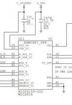
here is the updated bypass schematics, with added ESD protection for APU, SB IC and 5V OUT lines (alternatively can also add 5.6V Zener diode to protect HPD line). The Power Switch IC for 5V line is used to prevent TV/AV Receiver constantly getting power (from HDMI port) and searching/waiting for a video signal input when the system is off.
SOT23-5 and Zener diodes taken from PS4 system along with a resettable fuse, but can use any Power Switch IC (3.3-5.6V, with similar pinout) if have no access to PS4 donor board


SOT23-5 and Zener diodes taken from PS4 system along with a resettable fuse, but can use any Power Switch IC (3.3-5.6V, with similar pinout) if have no access to PS4 donor board

it's not a MOSFET, it's an ESD Protection and Signal Booster for HDMI Source IC, made by STMicroelectronics, and 740 is just a production date code (2017, week 40), the NF is a correct marking for the IC (D is for manufacturing location), but you can't buy it, because STMicroelectronics hasn't released it to the public yet (there is no datasheet for it), so at this moment you can only get it from a donor board
HDMI2C4-5F2
The pin definitions seems to differ from the QFN chip you listed earlier, HDMI2C1-6C1. How does R_SDA_IC/R_SCL_IC differ from SDA_IC/SCL_IC? Are Aux_P/N the same as HEAC+/-? Since the QFN doesn't have enable/select functionality, I guess those can be ignored.
Or maybe I should just ask, has anybody worked out a block diagram or schematic of U21? Also, is the same IC used in Xbox Series X? Interestingly, they have the same reference designator.
")
The funny and funny thing:
- In the ONE X you can easily find the HDMI IC but not the booster.
- In the ONE S you can easily find the booster but not the HDMI IC.
- In the ONE X you can easily find the HDMI IC but not the booster.
- In the ONE S you can easily find the booster but not the HDMI IC.
Did this qfn chip wired properly restore all the functionality of the xbox? Looking to do something like this on a xbox series x with a dead u21. I had it bypassed but looking to sell the console know and want full functionality.I just got home from vacation yesterday and just got it soldered on the test board now. Next onto figuring out the pinout.
View attachment 291931
How did you come across the part number? Are you sure about it? I asked a contact at ST but he only told me it was similar to HDMI2C4-5F2.For ONE X > HDMIDP1-5F6
It seems like U21 is mostly TVS diodes, buffers, and level shifters. It should be able to work—I wanted to try it as well but I ended up selling the Xbox Series X as it was (with video but unable to display 4K). I suspected there might have been something wonky with the I2C portion.Did this qfn chip wired properly restore all the functionality of the xbox? Looking to do something like this on a xbox series x with a dead u21. I had it bypassed but looking to sell the console know and want full functionality.
from schematicsHow did you come across the part number? Are you sure about it? I asked a contact at ST but he only told me it was similar to HDMI2C4-5F2.
It seems like U21 is mostly TVS diodes, buffers, and level shifters. It should be able to work—I wanted to try it as well but I ended up selling the Xbox Series X as it was (with video but unable to display 4K). I suspected there might have been something wonky with the I2C portion.
Attachments
For those looking to use HDMI2C1-6C1 in place of original U21 chip to have full functionality/video output capabilities, use the following guide to fix your system. Not all pins of the chip will be used, since we don't really care about CEC and HEAC/Utility lines (those lines are already protected on the motherboard by TVS diodes), all we care about is boosting CLK, DATA and HPD lines from 3.3V to 5V and getting 5V OUT on Pin 18 of HDMI port.
Difficulty: Advanced
Parts required: 1. HDMI2C1-6C1 chip. 2. QFN-16 breakout board or similar board capable of handling QFN-18 chip with 0.5mm pitch. 3. 0.1uF 10V (or 16V) 0402 capacitor and two 1.8k resistors. 4. Optional: Power Switch IC (found on PS4 board for 5V OUT/Pin 18 of HDMI port).
STEP 1. Prep: A) Secure HDMI2C1-6C1 chip to the breakout board with Pin 1 (FAULT) and Pin 14 (VDD_CEC) of the chip floating and not connected. B) On the breakout board: solder one side of the 1.8k resistors to the SDA and SCL points and link the other side of the resistors to the 5V_OUT rail. C) on the motherboard: replace C14 (for 5V_OUT) with 0.1uF 10V capacitor. D) link SCL_IC (E4) to R_SCL_IC (E5) and SDA_IC (E2) to R_SDA_IC (D5).
STEP 2. (OPTIONAL) HDMI2C1-6C1 chip is enabled as soon as VDD_5V comes in (which is a standby rail and always on when AC cord is plugged in to the power supply), so even if the system is not turned on - you will be getting 5V on Pin 18 (5V_OUT) of the HDMI port, and your TV will be constantly getting power and searching/awaiting video signal when the system is off. To remedy this - use Power Switch IC and wire it according to the diagram, this way our new VDD_5V will come in only when HDD is on.
STEP 3. Wire the motherboard to the breakout board (the way the chip is placed on the breakout board, the following pinout will be used: New TP1 is CEC_IC and TP16 is VDD_IC). Connect combined SDA_IC (E2/D5) to TP3, combined SCL_IC (E4/E5) to TP2, HPD_IC (B5) to TP4, HPD (A1) to TP8, SDA (C1) to TP9, SCL (D2) to TP 10, 5V_OUT (A3) to TP13, new VDD_5V to TP14, VDD_IC to TP16, and link TP11 to GND.
This guide is for Xbox One X motherboard, but obviously can be easily applied to Xbox Series S and X systems as well.
your contribution is appreciated although a connection diagram would be very useful, thinking a design of a pcb dedicated to this fixFor those looking to use HDMI2C1-6C1 in place of original U21 chip to have full functionality/video output capabilities, use the following guide to fix your system. Not all pins of the chip will be used, since we don't really care about CEC and HEAC/Utility lines (those lines are already protected on the motherboard by TVS diodes), all we care about is boosting CLK, DATA and HPD lines from 3.3V to 5V and getting 5V OUT on Pin 18 of HDMI port.
Difficulty: Advanced
Parts required: 1. HDMI2C1-6C1 chip. 2. QFN-16 breakout board or similar board capable of handling QFN-18 chip with 0.5mm pitch. 3. 0.1uF 10V (or 16V) 0402 capacitor and two 1.8k resistors. 4. Optional: Power Switch IC (found on PS4 board for 5V OUT/Pin 18 of HDMI port).
STEP 1. Prep: A) Secure HDMI2C1-6C1 chip to the breakout board with Pin 1 (FAULT) and Pin 14 (VDD_CEC) of the chip floating and not connected. B) On the breakout board: solder one side of the 1.8k resistors to the SDA and SCL points and link the other side of the resistors to the 5V_OUT rail. C) on the motherboard: replace C14 (for 5V_OUT) with 0.1uF 10V capacitor. D) link SCL_IC (E4) to R_SCL_IC (E5) and SDA_IC (E2) to R_SDA_IC (D5).
STEP 2. (OPTIONAL) HDMI2C1-6C1 chip is enabled as soon as VDD_5V comes in (which is a standby rail and always on when AC cord is plugged in to the power supply), so even if the system is not turned on - you will be getting 5V on Pin 18 (5V_OUT) of the HDMI port, and your TV will be constantly getting power and searching/awaiting video signal when the system is off. To remedy this - use Power Switch IC and wire it according to the diagram, this way our new VDD_5V will come in only when HDD is on.
STEP 3. Wire the motherboard to the breakout board (the way the chip is placed on the breakout board, the following pinout will be used: New TP1 is CEC_IC and TP16 is VDD_IC). Connect combined SDA_IC (E2/D5) to TP3, combined SCL_IC (E4/E5) to TP2, HPD_IC (B5) to TP4, HPD (A1) to TP8, SDA (C1) to TP9, SCL (D2) to TP 10, 5V_OUT (A3) to TP13, new VDD_5V to TP14, VDD_IC to TP16, and link TP11 to GND.
This guide is for Xbox One X motherboard, but obviously can be easily applied to Xbox Series S and X systems as well.
View attachment 323749View attachment 323750View attachment 323751

Appreciate the info. However, I can only get 640 x 480 rez out of this. The Pictures and instructions are not overly clear.
Can we ask for a propper connection diagram some wires are going under the mod board and the written instructions aren't quite correct from what I can see.
Can we ask for a propper connection diagram some wires are going under the mod board and the written instructions aren't quite correct from what I can see.
Last edited by AnHero,
That's great! I didn't know there were schematics out there. Thanks.from schematics
I had a similar thought. With a little flex board you could make it fairly simple to replace.your contribution is appreciated although a connection diagram would be very useful, thinking a design of a pcb dedicated to this fix


Similar threads
- Replies
- 0
- Views
- 237
- Replies
- 3
- Views
- 1K
- Replies
- 3
- Views
- 2K
- Replies
- 2
- Views
- 2K
Site & Scene News
New Hot Discussed
-
-
58K views
Nintendo Switch firmware 18.0.0 has been released
It's the first Nintendo Switch firmware update of 2024. Made available as of today is system software version 18.0.0, marking a new milestone. According to the patch... -
29K views
GitLab has taken down the Suyu Nintendo Switch emulator
Emulator takedowns continue. Not long after its first release, Suyu emulator has been removed from GitLab via a DMCA takedown. Suyu was a Nintendo Switch emulator... -
21K views
Atmosphere CFW for Switch updated to pre-release version 1.7.0, adds support for firmware 18.0.0
After a couple days of Nintendo releasing their 18.0.0 firmware update, @SciresM releases a brand new update to his Atmosphere NX custom firmware for the Nintendo...by ShadowOne333 94 -
18K views
Wii U and 3DS online services shutting down today, but Pretendo is here to save the day
Today, April 8th, 2024, at 4PM PT, marks the day in which Nintendo permanently ends support for both the 3DS and the Wii U online services, which include co-op play...by ShadowOne333 176 -
15K views
GBAtemp Exclusive Introducing tempBOT AI - your new virtual GBAtemp companion and aide (April Fools)
Hello, GBAtemp members! After a prolonged absence, I am delighted to announce my return and upgraded form to you today... Introducing tempBOT AI 🤖 As the embodiment... -
12K views
Pokemon fangame hosting website "Relic Castle" taken down by The Pokemon Company
Yet another casualty goes down in the never-ending battle of copyright enforcement, and this time, it hit a big website which was the host for many fangames based and...by ShadowOne333 65 -
11K views
MisterFPGA has been updated to include an official release for its Nintendo 64 core
The highly popular and accurate FPGA hardware, MisterFGPA, has received today a brand new update with a long-awaited feature, or rather, a new core for hardcore...by ShadowOne333 51 -
11K views
Apple is being sued for antitrust violations by the Department of Justice of the US
The 2nd biggest technology company in the world, Apple, is being sued by none other than the Department of Justice of the United States, filed for antitrust...by ShadowOne333 80 -
10K views
The first retro emulator hits Apple's App Store, but you should probably avoid it
With Apple having recently updated their guidelines for the App Store, iOS users have been left to speculate on specific wording and whether retro emulators as we... -
9K views
"TMNT: The Hyperstone Heist" for the SEGA Genesis / Mega Drive gets a brand new DX romhack with new features
The romhacking community is always a source for new ways to play retro games, from completely new levels or stages, characters, quality of life improvements, to flat...by ShadowOne333 36
-
-
-
223 replies
Nintendo Switch firmware 18.0.0 has been released
It's the first Nintendo Switch firmware update of 2024. Made available as of today is system software version 18.0.0, marking a new milestone. According to the patch...by Chary -
176 replies
Wii U and 3DS online services shutting down today, but Pretendo is here to save the day
Today, April 8th, 2024, at 4PM PT, marks the day in which Nintendo permanently ends support for both the 3DS and the Wii U online services, which include co-op play...by ShadowOne333 -
169 replies
GBAtemp Exclusive Introducing tempBOT AI - your new virtual GBAtemp companion and aide (April Fools)
Hello, GBAtemp members! After a prolonged absence, I am delighted to announce my return and upgraded form to you today... Introducing tempBOT AI 🤖 As the embodiment...by tempBOT -
146 replies
GitLab has taken down the Suyu Nintendo Switch emulator
Emulator takedowns continue. Not long after its first release, Suyu emulator has been removed from GitLab via a DMCA takedown. Suyu was a Nintendo Switch emulator...by Chary -
96 replies
The first retro emulator hits Apple's App Store, but you should probably avoid it
With Apple having recently updated their guidelines for the App Store, iOS users have been left to speculate on specific wording and whether retro emulators as we...by Scarlet -
94 replies
Atmosphere CFW for Switch updated to pre-release version 1.7.0, adds support for firmware 18.0.0
After a couple days of Nintendo releasing their 18.0.0 firmware update, @SciresM releases a brand new update to his Atmosphere NX custom firmware for the Nintendo...by ShadowOne333 -
80 replies
Apple is being sued for antitrust violations by the Department of Justice of the US
The 2nd biggest technology company in the world, Apple, is being sued by none other than the Department of Justice of the United States, filed for antitrust...by ShadowOne333 -
74 replies
Delta emulator now available on the App Store for iOS
The time has finally come, and after many, many years (if not decades) of Apple users having to side load emulator apps into their iOS devices through unofficial...by ShadowOne333 -
65 replies
Pokemon fangame hosting website "Relic Castle" taken down by The Pokemon Company
Yet another casualty goes down in the never-ending battle of copyright enforcement, and this time, it hit a big website which was the host for many fangames based and...by ShadowOne333 -
53 replies
Nintendo "Indie World" stream announced for April 17th, 2024
Nintendo has recently announced through their social media accounts that a new Indie World stream will be airing tomorrow, scheduled for April 17th, 2024 at 7 a.m. PT...by ShadowOne333
-
General chit-chat
- No one is chatting at the moment.
-
-
-
-
-
-
-
-
-
-
-
-
-
-
-
-
-
-
-
-
 @
RedColoredStars:
There is an actual trailer with footage too. lol. Going to watch it tonight. Grabbed it from... a place.
@
RedColoredStars:
There is an actual trailer with footage too. lol. Going to watch it tonight. Grabbed it from... a place. -
-
 @
SylverReZ:
@Psionic Roshambo, JonTron's back yet again until he disappears into the void for another 6 or so months.+1
@
SylverReZ:
@Psionic Roshambo, JonTron's back yet again until he disappears into the void for another 6 or so months.+1 -
-
-