Tutorial  Updated

How to flash the HWFLY Clone chips

See below for updates.

IF YOU BREAK YOUR BOOT0 PIN. DO NOT DM ME ASKING FOR HELP. THAT'S IT. YOU BREAK THAT PIN AND YOU CANT FLASH. YOUR CHIP IS STUCK WITH WHATEVER HWFLY PUT ON IT


Pre-requisites:


  • Raspberry Pi Zero W
    • You may use another flasher if you desire.
  • Pinout Diagram
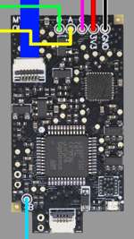
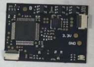
  • Modchip Diagram
  • FULL_CHIP_STOCK.bin
  • Modchip Diagram, find the PA9(TX) and the PA10(RX) pins on your modchip, and do the following:
    • Connect GPIO14(TX) on your Raspberry Pi Zero W to the PA10(RX) pin on your modchip.
    • Connect GPIO15(RX) on your Raspberry Pi Zero W to the PA9(TX) pin on your modchip.

  1. Solder a wire to each of the following pinouts on the Raspberry Pi Zero W:
    • 3.3V
    • Ground
    • GPIO 14 (UART TX)
    • GPIO 15 (UART RX)
  2. Do the following to prepare the modchip:
    1. Lift pin 44 (also known as BOOT0).
    2. You will need a way to power the chip, so you need to find two 3.3v points. It can be on a MOSFET, but it will differ based on the revision of the modchip.
    3. Connect Ground on your Raspberry Pi Zero W to the Ground pin on your modchip.
    4. Check the Modchip Diagram, find the PA9(TX) and the PA10(RX) pins on your modchip, and do the following:
      • Connect GPIO14(TX) on your Raspberry Pi Zero W to the PA10(RX) pin on your modchip.
      • Connect GPIO15(RX) on your Raspberry Pi Zero W to the PA9(TX) pin on your modchip.
  3. Boot your Raspberry Pi Zero W and do the following:
    1. In the terminal, type the following command, and press enter:
      Bash:
      sudo nano /boot/config.txt
    2. Add the following line to the end of the file:
      INI:
      dtoverlay=pi3-miniuart-bt
    3. Press CTRL + X to save and exit the editor.
    4. In the terminal, type the following command, and press enter:
      Bash:
      sudo nano /boot/cmdline.txt
    5. Remove the following line from the file:
      INI:
      console=serial0,115200
    6. Press CTRL + X to save and exit the editor.
    7. Restart your Raspberry Pi with this command
      Bash:
      sudo /sbin/reboot
    8. In the terminal, type the following commands, and press enter after each command:

      Bash:
      git clone https://github.com/Pheeeeenom/stm32flash.git
      cd stm32flash
      sudo make install
  4. Now you will flash the modchip.
    Note: This will remove read protection, and the modchip will wipe itself (that is what we want).
    1. In the terminal, type the following command, and press enter:
      Bash:
      stm32flash -k /dev/serial0
    2. Now to flash Spacecraft-NX Version 0.2.0, type the following, and press enter:
      Bash:
      stm32flash -v -w ./FULL_CHIP_STOCK.bin /dev/serial0
  5. Once you're done flashing your modchip, remove the wiring from the modchip, and restore the 3.3v pin on the modchip to its original position.

Please post pictures of your work here to further the identification of the different board revisions!


UPDATE: So it seems like stitching the spacecraft bootloader and firmware together from the repo causes unstable glitching behaviors. For now, consistent glitching behavior works with this bootload/firmware combo.
This is the original file on the OLED variant chip which has 0.2.0 spacecraft. As for glitching, I'll figure it out, give me some time...unless someone else wants to hop in and reverse the differences.

For now, this at least solves the 0.1.0 HWFLY gen 3 issue. More to come.

UPDATE 2: This is only going to work on some HWFLY chips. Older ones use higher protection than the new revisions that seem to use the QFN FPGA.

UPDATE 3: This should fully work on OLED modchips with the QFN FPGA. https://github.com/Pheeeeenom/firmware
 
Last edited by Mena,

lufeig

Well-Known Member
Member
Joined
Oct 22, 2009
Messages
306
Trophies
1
Age
45
Location
São Paulo, Brazil
XP
1,057
Country
Brazil
@JaRocker

I don’t have a Mariko PCB to help you, but I would advise you to use a multimeter to find the resistor yourself.

It will be faster than waiting for someone do it for you. And doing it by yourself, you’ll have confidence that you got the right resistor.
 

FR0ZN

Well-Known Member
Member
Joined
Nov 2, 2013
Messages
1,372
Trophies
1
Age
37
XP
3,850
Country
United States
hey where can i find the cmd point in the older switch motherboard.
I don't know which one it is I'm trying to use this board as a donor for my OLED
I'm 99.9% sure, that these 4 points are alternative CMD points:

1643323248938.png
 

JaRocker

Well-Known Member
Member
Joined
May 3, 2018
Messages
341
Trophies
0
XP
1,486
Country
Jamaica
@JaRocker

I don’t have a Mariko PCB to help you, but I would advise you to use a multimeter to find the resistor yourself.

It will be faster than waiting for someone do it for you. And doing it by yourself, you’ll have confidence that you got the right resistor.
my multimeter isn't working idk what's up with it
 

boston909

Member
Newcomer
Joined
Jan 10, 2022
Messages
11
Trophies
0
Age
35
XP
55
Country
United Kingdom
1 consider that there are some OLED modchips w/ USB that are not compatible with this method

2 I can’t comment on sd card compatibility, I have a 512GB Lexar and never had any problem, never got a single NOSD screen

3 glitching times with r021 are consistently better on my Switch. same behavior is observed on the Switch of another user here, in fact I flashed r021 following his report about it

4 I don’t feel comfortable to recommend flashing r021 because there are still risks involved in the process. Glitching on stock fw works, but on r021 it is optimized. I did it because I know I wouldn’t sleep well if I didn’t. LOL. But considering the risks, I would say it’s up to you to decide if it’s worth it or not. 😉
Thanks lufeig - I'll ask the modder to just see how things stand with the stock 0.2.0, in terms of which SD cards it accepts, before thinking about flashing sthetix's r021 firmware. :)

EDIT: I purchased this type of OLED chip:
2My3a3.png


(as opposed to this type):
w6Vsh4.png


So I'm hoping mine can be flashed with sthetix's r021 firmware or Mena's SD card compatible firmware. I'll wait to see what my UK modder says. :)
 
Last edited by boston909,
  • Like
Reactions: lufeig

URBANsUNITED

Active Member
Newcomer
Joined
Oct 17, 2015
Messages
32
Trophies
0
Age
49
XP
364
Country
Germany
Hi! Does anybody know if a broken xs lite chip is rescue able?
A HWFly works with the same soldered flex cables, the sx lite doesn't. The SX Lite boots straight into original FW

Can I flash it with the instructions from page 1 too? Or is there something for sx lite directly available?

Btw. I can't see any damages on the chip mainboard.

Thanks

URBANsUNITED
 

Attachments

  • vid_20220121_150517_1_ (1).mp4
    28.5 MB

URBANsUNITED

Active Member
Newcomer
Joined
Oct 17, 2015
Messages
32
Trophies
0
Age
49
XP
364
Country
Germany
I did, but it didn‘t. The flash went well without issues. But I don’t know if it also flashes the bootloader…
And yes, it‘s a real sx lite
 

kylum

Well-Known Member
Member
Joined
Dec 8, 2008
Messages
394
Trophies
1
XP
1,477
Country
United States
I did, but it didn‘t. The flash went well without issues. But I don’t know if it also flashes the bootloader…
And yes, it‘s a real sx lite
You can flash the bootloader and firmware. They are separate files! Did you try flashing bootloader.bin or just firmware.bin
 

URBANsUNITED

Active Member
Newcomer
Joined
Oct 17, 2015
Messages
32
Trophies
0
Age
49
XP
364
Country
Germany
Used the flash.bat and there it flashes the bootloader first.
All strange…
Will the gd link ob flasher flash the chip different? Or a rpi?
Can a chip be broken directly?
 

kylum

Well-Known Member
Member
Joined
Dec 8, 2008
Messages
394
Trophies
1
XP
1,477
Country
United States
Used the flash.bat and there it flashes the bootloader first.
All strange…
Will the gd link ob flasher flash the chip different? Or a rpi?
Can a chip be broken directly?
Flash.bat works just fine. You should have seen dashes across the screen while it did it’s thing. GD-link and ST-links is done differently and will need the apppropriate software, susessful writes are confirmed through the software. Same with RPI. If you got a successful write through one way and it’s still bricked I don’t believe the other ways will magically make it work. But I could be wrong
 
Last edited by kylum,

mocthulang

Member
Newcomer
Joined
Jan 21, 2022
Messages
13
Trophies
0
Age
42
XP
100
Country
Vietnam
Hi! Does anybody know if a broken xs lite chip is rescue able?
A HWFly works with the same soldered flex cables, the sx lite doesn't. The SX Lite boots straight into original FW

Can I flash it with the instructions from page 1 too? Or is there something for sx lite directly available?

Btw. I can't see any damages on the chip mainboard.

Thanks

URBANsUNITED
yours is not tx's modchip, it's hwfly lite
 

URBANsUNITED

Active Member
Newcomer
Joined
Oct 17, 2015
Messages
32
Trophies
0
Age
49
XP
364
Country
Germany
I bought it way before HWfly poped out. Bought 2020-11-30 and the HWfly annoucement was in 05/06-2021.
But you are right, it looks like an HWFly modchip. Strange...
 
Last edited by URBANsUNITED,

leerz

Well-Known Member
Member
Joined
Jan 11, 2015
Messages
753
Trophies
0
Age
36
Location
Makati
Website
leerz25.sitesled.com
XP
2,175
Country
I did, but it didn‘t. The flash went well without issues. But I don’t know if it also flashes the bootloader…
And yes, it‘s a real sx lite
what's the led status of your sxlite? does it stay white? if yes, then clk line isn't connected right, that being hooked from the board of your lite will prevent ofw booting hence if it goes straight, then it's not connected.
 

URBANsUNITED

Active Member
Newcomer
Joined
Oct 17, 2015
Messages
32
Trophies
0
Age
49
XP
364
Country
Germany
what's the led status of your sxlite? does it stay white? if yes, then clk line isn't connected right, that being hooked from the board of your lite will prevent ofw booting hence if it goes straight, then it's not connected.
Please check the video.
 

Site & Scene News

Popular threads in this forum

General chit-chat
Help Users
  • No one is chatting at the moment.
    K3Nv2 @ K3Nv2: It's mostly the ones that are just pictures and no instructions at all