


After installing modchip SX Lite, the fan stopped spinning, joycons do not charge. Otherwise, Switch works fine. Tell me, what could be the reason?
You are using an out of date browser. It may not display this or other websites correctly.
You should upgrade or use an alternative browser.
You should upgrade or use an alternative browser.
Switch OLED. The fan is not working and joycons are not charging
- Thread starter heinrich_frei
- Start date
- Views 8,673
- Replies 30
- Likes 1


I installed itdid you install or someone else installed for you ?
Attachments
Last edited by heinrich_frei,

Do the joycons function when you disable bluetooth(/airplane mode)?
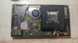
Soldering looks neither great nor terrible, but this is really asking for trouble:

The thermal paste of running everywhere indicates either very low viscosity or too much of it applied. Should probably clean that up.
Soldering looks neither great nor terrible, but this is really asking for trouble:
The thermal paste of running everywhere indicates either very low viscosity or too much of it applied. Should probably clean that up.
Yes. Joycons work without Bluetooth in airplane modeDo the joycons function when you disable bluetooth(/airplane mode)?
Ok. I'll try to fix the listed problems and posted about the result
The fan and joycons charge of the same 5V coming from a boost ic. See if there's a short in either the rails or fan by disconnecting 2 out of 3 and checking if the remaining one works. If not, either the boost ic or some protection diode may be bad.
By the way, how do you test that the fan doesn't work? Can you make it spin on demand normally?
By the way, how do you test that the fan doesn't work? Can you make it spin on demand normally?
I watch the fan speed in overlay. The fan doesn't work even at 100% RPMBy the way, how do you test that the fan doesn't work?

Airplane mode doesn't turn off Bluetooth I think.Yes. Joycons work without Bluetooth in airplane mode
Ok. I'll try to fix the listed problems and posted about the result
It's possible the issue is as simple as the JoyCon rail ribbon cables not being plugged in all the way or being damaged but you shouldn't even have to remove or unplug the rails to install a chip.
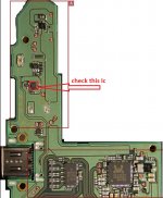
The problem could not be solved. Do you mean this ic? If yes, then I can't find it on Switch OLEDThere is one supply shared by the joycon rails and the fan.
P. S. I measured the voltage of the fan connector, it is 0v
Attachments
YesDoes it still measure 0V when both joycon rails and the fan are unplugged?
What's the resistance over the 5v pin of the fan and GND? Can you trace the 5v point to any of the ic's in continuity mode, and check if any nearby capacitors are shorted around this chip?
Sorry I been gone so long. I measured in continuity mode and got to this chip. There is no voltage at this point, but I didn't find any shorted capacitors nearby.
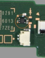
P.S. I also noticed that the element in the second picture passes electricity in both directions. Is this how it should be?
P.S. I also noticed that the element in the second picture passes electricity in both directions. Is this how it should be?
Attachments
Last edited by heinrich_frei,
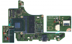
Hi, I've done some tracing. As suspected there is indeed a ~5V supply that is used for charging the joycons and PWM on the fan. It should be really simple to fix.
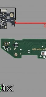
See attached diagram. The square black IC on the left of the SoC is a boost regulator that pumps up the ~3.7V from the battery to 5.3V using a MAX8969EWL53+.
Please check whether the following (with battery/USB detached):
- resistance to GND between the 5.3V point near the MAX8969, should be ~3k Ohms
- continuity between 3 marked 5.3V points (capacitor near SoC, pin on fan connector, capacitor near right joycon switch), should be ~0 Ohms
If that's good, then check, with battery attached. Wait for the switch to be fully booted, else the regulator is not enabled:
- voltage on the 3.7V point marked near the MAX8969, should be around 3.7V
- voltage on the 5.3V points, should be 5.3V obviously
If there is no short on the 5.3V rails to GND but also no power, then reflow this chip. If that does not help, we must replace it.
Attachments
Thank you for your hard work.
Good.- resistance to GND between the 5.3V point near the MAX8969, should be ~3k Ohms
Good.- continuity between 3 marked 5.3V points (capacitor near SoC, pin on fan connector, capacitor near right joycon
Good.- voltage on the 3.7V point marked near the MAX8969, should be around 3.7V
0v at all three points. MAX8969 looks damaged. MAX8969EWL53+ T chip suitable for replacement?- voltage on the 5.3V points, should be 5.3V obviously
Similar threads
- Replies
- 2
- Views
- 334
- Replies
- 0
- Views
- 298
- Replies
- 1
- Views
- 711
- Replies
- 2
- Views
- 603
Site & Scene News
New Hot Discussed
-
-
62K views
Nintendo Switch firmware 18.0.0 has been released
It's the first Nintendo Switch firmware update of 2024. Made available as of today is system software version 18.0.0, marking a new milestone. According to the patch... -
23K views
Atmosphere CFW for Switch updated to pre-release version 1.7.0, adds support for firmware 18.0.0
After a couple days of Nintendo releasing their 18.0.0 firmware update, @SciresM releases a brand new update to his Atmosphere NX custom firmware for the Nintendo...by ShadowOne333 94 -
20K views
Wii U and 3DS online services shutting down today, but Pretendo is here to save the day
Today, April 8th, 2024, at 4PM PT, marks the day in which Nintendo permanently ends support for both the 3DS and the Wii U online services, which include co-op play...by ShadowOne333 179 -
16K views
GBAtemp Exclusive Introducing tempBOT AI - your new virtual GBAtemp companion and aide (April Fools)
Hello, GBAtemp members! After a prolonged absence, I am delighted to announce my return and upgraded form to you today... Introducing tempBOT AI 🤖 As the embodiment... -
12K views
Pokemon fangame hosting website "Relic Castle" taken down by The Pokemon Company
Yet another casualty goes down in the never-ending battle of copyright enforcement, and this time, it hit a big website which was the host for many fangames based and...by ShadowOne333 65 -
12K views
The first retro emulator hits Apple's App Store, but you should probably avoid it
With Apple having recently updated their guidelines for the App Store, iOS users have been left to speculate on specific wording and whether retro emulators as we... -
12K views
MisterFPGA has been updated to include an official release for its Nintendo 64 core
The highly popular and accurate FPGA hardware, MisterFGPA, has received today a brand new update with a long-awaited feature, or rather, a new core for hardcore...by ShadowOne333 53 -
11K views
Delta emulator now available on the App Store for iOS
The time has finally come, and after many, many years (if not decades) of Apple users having to side load emulator apps into their iOS devices through unofficial...by ShadowOne333 95 -
10K views
"TMNT: The Hyperstone Heist" for the SEGA Genesis / Mega Drive gets a brand new DX romhack with new features
The romhacking community is always a source for new ways to play retro games, from completely new levels or stages, characters, quality of life improvements, to flat...by ShadowOne333 36 -
9K views
Anbernic announces RG35XX 2024 Edition retro handheld
Retro handheld manufacturer Anbernic is releasing a refreshed model of its RG35XX handheld line. This new model, named RG35XX 2024 Edition, features the same...
-
-
-
225 replies
Nintendo Switch firmware 18.0.0 has been released
It's the first Nintendo Switch firmware update of 2024. Made available as of today is system software version 18.0.0, marking a new milestone. According to the patch...by Chary -
179 replies
Wii U and 3DS online services shutting down today, but Pretendo is here to save the day
Today, April 8th, 2024, at 4PM PT, marks the day in which Nintendo permanently ends support for both the 3DS and the Wii U online services, which include co-op play...by ShadowOne333 -
169 replies
GBAtemp Exclusive Introducing tempBOT AI - your new virtual GBAtemp companion and aide (April Fools)
Hello, GBAtemp members! After a prolonged absence, I am delighted to announce my return and upgraded form to you today... Introducing tempBOT AI 🤖 As the embodiment...by tempBOT -
96 replies
The first retro emulator hits Apple's App Store, but you should probably avoid it
With Apple having recently updated their guidelines for the App Store, iOS users have been left to speculate on specific wording and whether retro emulators as we...by Scarlet -
95 replies
Delta emulator now available on the App Store for iOS
The time has finally come, and after many, many years (if not decades) of Apple users having to side load emulator apps into their iOS devices through unofficial...by ShadowOne333 -
94 replies
Atmosphere CFW for Switch updated to pre-release version 1.7.0, adds support for firmware 18.0.0
After a couple days of Nintendo releasing their 18.0.0 firmware update, @SciresM releases a brand new update to his Atmosphere NX custom firmware for the Nintendo...by ShadowOne333 -
65 replies
Pokemon fangame hosting website "Relic Castle" taken down by The Pokemon Company
Yet another casualty goes down in the never-ending battle of copyright enforcement, and this time, it hit a big website which was the host for many fangames based and...by ShadowOne333 -
53 replies
Nintendo Switch firmware update 18.0.1 has been released
A new Nintendo Switch firmware update is here. System software version 18.0.1 has been released. This update offers the typical stability features as all other...by Chary -
53 replies
Nintendo "Indie World" stream announced for April 17th, 2024
Nintendo has recently announced through their social media accounts that a new Indie World stream will be airing tomorrow, scheduled for April 17th, 2024 at 7 a.m. PT...by ShadowOne333 -
53 replies
MisterFPGA has been updated to include an official release for its Nintendo 64 core
The highly popular and accurate FPGA hardware, MisterFGPA, has received today a brand new update with a long-awaited feature, or rather, a new core for hardcore...by ShadowOne333
-
Popular threads in this forum
General chit-chat
-
S
salazarcosplay
Loading…
-
 K3Nv2
Loading…
K3Nv2
Loading… -
 realtimesave
Loading…
realtimesave
Loading… -
 Psionic Roshambo
Loading…
Psionic Roshambo
Loading…

