PS1/2 Ps2 fat power supply unit repair guide.

AxelMad

Member
OP
Newcomer
Joined
May 19, 2020
Messages
7
Trophies
0
Age
34
XP
111
Country
Spain
Greetings gentlemen of GBAtemp.

My name is Axel, im rather new around here, and today i wanted to share my experience with the PS2 Fat power supply unit.

Disclaymer.
I will take for granted that anyone who will follow this instructions has a minimum of electronics knowledge and respects how dangerous it can get if taken lightly. I will not be responsable if you go around playing with high voltages and get hurt or break anything. Also, to make these diagnostics and repairs you have to dissasemble your PS2 in order to take the power board out. If you have issues with your power supply and dont know electronics well enough to feel confident about this, you can just buy a replacement PSU for 15$ aproximately online and avoid this completly. IF anyone is wondering why would i bother repairing these old PSUs instead of buying cheap new ones is simply because i like my hardware to be original, and repairing something that would be otherwise be thrown out is very satisfying to me.


I will be referring to the image to make everything easier and more clear.
IMG_20200522_151756.jpg


Symptoms:
Ps2 console wont turn on, no red light and no reaction to ON or RESET buttons in any way when the console is plugged in and the switch on the back is on.


How to confirm if your PSU is having issues:
We will need a Multimeter or Tester.
Your unit's task is to take in the 120v/240v AC from your home's electricty and turn it into @24V DC.
To test if your unit is doing it's job, place your unit on a non conductive surface (wood,plastic), plug in the unit (please be ware; DO NOT TOUCH Point A , is LIVE with 120v/204v), and switch it on. Now with a multimeter check the 1st socket from the left and the 4th socket from the left for DC Voltage on Point B.
If the multimeter shows around 24 volts DC, then the unit is fine and working propperly, if the multimeter shows 0v DC then we have some work to do.
TURN OFF AND UNPLUG BEFORE CONTINUING


Now that we confirmed that the unit is not working, let us see the possible issues.

Possible issues:
1 - Burned out fuse
2 - Blown capacitors
3 - Capacitors lost capacitance
4 - Octocoupler is not workin
5 - Zener Diodes / Diodes broke
6 - Mosfets broke

The Fuse
31929-31-fusible-ceramica-25-a-250v-tipo-temporizado-5x20-mm-simon-31-frontal.jpg

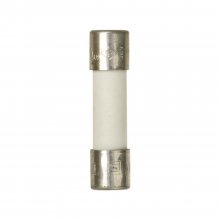
The first thing to test is the F1 Fuse (Point C), simply set the multimeter on "continuity" or "resistance (Ω)" and if the multimeter beeps or shows 0 Ω then the fuse is OK and working.
In case the fuse presents no continuity it would mean it is burned and needs to be replaced. In my case, all units i repaired were PAL units and the fuse was 250V 2.5A but these may differ for other regions, so be sure to check your fuse before you buy a replacement, if you don't find the exact same fuse, buy one slightly lower as close to the original as possible.


Blown Capacitors
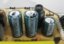
Most of the time blown capacitors are quite easy to identify as their phisical appearence change and some even smell bad. If a capacitor is showing a "bulge" on top, it means it most certainly needs replacement. To test them with the multimeter, connect one pin to ground or negative (3rd or 4th socket on point B) and test both "legs" of the capacitor on the under side of the board. One leg should give continuity to ground/negative while the other should NOT give continuity (positve "leg" should not). If one capacitor does give continuity in both legs, means is broken and needs to be replaced.
In case you need to replace one of these capacitors, check what is written on them, the Capacitance, the volts, and the temperature. for istance: 680Uf - 16V - 105º.
repairing-switching-power-supply-3.jpg


Capacitors lost capacitance
This is the absolutely most common issue i have encountered with these power boards
.
Mainly C20 and C3 (point D and E) tend to lose capacitance making it impossible for the board to do its job.
To propperly test the capacitance of a capacitor is kind of quirky afaik, so the next best thing is to simply buy one of each online and change them both. I bought 2 packs of 10 each for about 2 euros, and almost finished them due to how common this issue is, so in any case, sooner or later, you may need to replace them so why not now that you are working on it.


Octocoupler.
This spider looking fella only troubled me once, but is worth checking out nontheless.
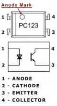
In my case the OC was a PC123 equivalent.
You can google how to test an octocoupler. Is quite simple.
pc123-163x300.jpg


Zener diodes / Diodes.
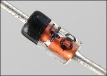
Set your multimeter to continuity and test the diodes both way. A working diode gives continuity in only "one way". The diodes have a "direction" in which they block or allow current. Test your diode both ways, in one way it should block the current while in the other it should allow it. If the diode gives continuity both ways, or gives no cintuinity at all, is broken. The most common diode to fail is ZD1 and ZD3. You may also want to check the top left corner diodes D10 D9 D7 D8. Testing all the diodes present in the circuit is not a bad idea, just an extra security and is often among the first things you want to rule out.
unnamed.jpg

Broken mosfets.

I never found an issue with these but i've heard of people that did.
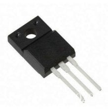
In the picture you will notice 2 heatsinks running vertically near the capacitors on the left and near the Zener diodes. If everything else you have tested up until now is working well and you still have issues, these little guys may be the problem.
HTB18NzNXEvrK1RjSspcq6zzSXXa2.jpg


If you have any doubts please ask, I am not an expert, but will gladly help in what i can.

EDIT: I may take some time to get back here but I do keep an eye on this thread for questions.

I will try to answer some questions encountered here and on my reddit post.

Q1 - Can i swap my broken power supply with the power supply of another ps2?
A1 - Technically you could but you will probably run into some issues. From one revision to another, or model to another, the PSU could change in phisical shape and probably won't fit into the console correctly. The 12V pins socket will be moved and so will be the L-N connector. This will make it practically impossible to re-assemble the unit correctly giving you some frankentseiny-ps2.

Q2 - I Can't repair my psu, i can't find a replacement, what do i do?

A2 - You can buy an external PSU with the correct values and hook it up to the console's input pins. I've done this to test consoles and check if it really was the PSU causing issues and it worked fine. You can check original board for the values you need for the PSU.
Im talking about this kind of external PSU.
61B1hbooSbL._AC_SL1200_.jpg


Q3 - Information about the MOSFET.
A3 - I honestly can't recall the specs and i can't currently check, if you happen to need this information you can take the mosfet out of the board and see what's written on it, googling this should bring info up.
Example: On one of the sides, there is stuff written, one of these is the name of the brand, the voltage and the model, look for the model name.
f99c48b02ec31af0b1687ce85bdbdf1a.png
 
Last edited by AxelMad,

Alexander1970

XP not matters.
Member
Joined
Nov 8, 2018
Messages
14,973
Trophies
3
Location
Austria
XP
2,495
Country
Austria
Greetings gentlemen of GBAtemp.

My name is Axel, im rather new around here, and today i wanted to share my experience with the PS2 Fat power supply unit.

Disclaymer.
I will take for granted that anyone who will follow this instructions has a minimum of electronics knowledge and respects how dangerous it can get if taken lightly. I will not be responsable if you go around playing with high voltages and get hurt or break anything. Also, to make these diagnostics and repairs you have to dissasemble your PS2 in order to take the power board out. If you have issues with your power supply and dont know electronics well enough to feel confident about this, you can just buy a replacement PSU for 15$ aproximately online and avoid this completly. IF anyone is wondering why would i bother repairing these old PSUs instead of buying cheap new ones is simply because i like my hardware to be original, and repairing something that would be otherwise be thrown out is very satisfying to me.


I will be referring to the image to make everything easier and more clear.
View attachment 210059


Symptoms:
Ps2 console wont turn on, no red light and no reaction to ON or RESET buttons in any way when the console is plugged in and the switch on the back is on.


How to confirm if your PSU is having issues:
We will need a Multimeter or Tester.
Your unit's task is to take in the 120v/240v AC from your home's electricty and turn it into @24V DC.
To test if your unit is doing it's job, place your unit on a non conductive surface (wood,plastic), plug in the unit (please be ware; DO NOT TOUCH Point A , is LIVE with 120v/204v), and switch it on. Now with a multimeter check the 1st socket from the left and the 4th socket from the left for DC Voltage on Point B.
If the multimeter shows around 24 volts DC, then the unit is fine and working propperly, if the multimeter shows 0v DC then we have some work to do.
TURN OFF AND UNPLUG BEFORE CONTINUING


Now that we confirmed that the unit is not working, let us see the possible issues.

Possible issues:
1 - Burned out fuse
2 - Blown capacitors
3 - Capacitors lost capacitance
4 - Octocoupler is not workin
5 - Zener Diodes / Diodes broke
6 - Mosfets broke

The Fuse
View attachment 210053

The first thing to test is the F1 Fuse (Point C), simply set the multimeter on "continuity" or "resistance (Ω)" and if the multimeter beeps or shows 0 Ω then the fuse is OK and working.
In case the fuse presents no continuity it would mean it is burned and needs to be replaced. In my case, all units i repaired were PAL units and the fuse was 250V 2.5A but these may differ for other regions, so be sure to check your fuse before you buy a replacement, if you don't find the exact same fuse, buy one slightly lower as close to the original as possible.


Blown Capacitors
Most of the time blown capacitors are quite easy to identify as their phisical appearence change and some even smell bad. If a capacitor is showing a "bulge" on top, it means it most certainly needs replacement. To test them with the multimeter, connect one pin to ground or negative (3rd or 4th socket on point B) and test both "legs" of the capacitor on the under side of the board. One leg should give continuity to ground/negative while the other should NOT give continuity (positve "leg" should not). If one capacitor does give continuity in both legs, means is broken and needs to be replaced.
In case you need to replace one of these capacitors, check what is written on them, the Capacitance, the volts, and the temperature. for istance: 680Uf - 16V - 105º.
View attachment 210049


Capacitors lost capacitance
This is the absolutely most common issue i have encountered with these power boards
.
Mainly C20 and C3 (point D and E) tend to lose capacitance making it impossible for the board to do its job.
To propperly test the capacitance of a capacitor is kind of quirky afaik, so the next best thing is to simply buy one of each online and change them both. I bought 2 packs of 10 each for about 2 euros, and almost finished them due to how common this issue is, so in any case, sooner or later, you may need to replace them so why not now that you are working on it.


Octocoupler.

This spider looking fella only troubled me once, but is worth checking out nontheless.
In my case the OC was a PC123 equivalent.
You can google how to test an octocoupler. Is quite simple.
View attachment 210055


Zener diodes / Diodes.

Set your multimeter to continuity and test the diodes both way. A working diode gives continuity in only "one way". The diodes have a "direction" in which they block or allow current. Test your diode both ways, in one way it should block the current while in the other it should allow it. If the diode gives continuity both ways, or gives no cintuinity at all, is broken. The most common diode to fail is ZD1 and ZD3. You may also want to check the top left corner diodes D10 D9 D7 D8. Testing all the diodes present in the circuit is not a bad idea, just an extra security and is often among the first things you want to rule out.
View attachment 210057

Broken mosfets.

I never found an issue with these but i've heard of people that did.
In the picture you will notice 2 heatsinks running vertically near the capacitors on the left and near the Zener diodes. If everything else you have tested up until now is working well and you still have issues, these little guys may be the problem.
View attachment 210058


If you have any doubts please ask, I am not an expert, but will gladly help in what i can.

Hello and welcome to GBAtemp.:D

Thank you for this great and good explained Step by Step Tutorial.

Considering the Age from the PlayStation 2 we will maybe need it......in the next Time.:(
Thank you for your Contribution and have a great Time here.

Thank you.:)
 

debilausaure

New Member
Newbie
Joined
Jun 29, 2017
Messages
1
Trophies
0
Age
32
XP
55
Country
Algeria
Hi :)! I recently took my ps2 out of its box and there was no standby redlight when plugged in.

(I happen to have the exact same power supply board as you do, so hopefully I will be able to make sense ^_^)

I followed your post (which is really helpful for a newbie like me, thank you !), and figured that at least one diode is obviously defective as it is shorted (ZD1). I tested the other diodes as well, and some of them were not shorted but gave continuity in both ways (~530 ohms in forward bias which looks ok, but between 800 and 1200 ohms in reverse bias). The said diodes are ZD2, ZD3, ZD51 and D4.

I am really unsure about whether these are indeed defective or if that is to be expected. Hence I am unsure about if I should replace them or not. Do you have any idea ?

Besides, I really don't know how to identify the diodes either :ph34r: How do you know which replacements to buy ? Do you have a datasheet of the board and its components or is it written on the components once you unsolder them ?

Once again great post, it really was helpful to me :yay:. Thank you !
 
  • Like
Reactions: Alexander1970

MushGuy

Well-Known Member
Member
Joined
Feb 11, 2010
Messages
1,280
Trophies
1
XP
2,576
Country
United States
Funny that this thread popped up. Just today, my PS2 stopped working due to a power outage. Is it OK to get a new power supply from eBay? How good is one from China?
 
  • Like
Reactions: Alexander1970

AxelMad

Member
OP
Newcomer
Joined
May 19, 2020
Messages
7
Trophies
0
Age
34
XP
111
Country
Spain
Funny that this thread popped up. Just today, my PS2 stopped working due to a power outage. Is it OK to get a new power supply from eBay? How good is one from China?
Hi, if you don't know what you are doing the cheap power supplies are the best option. Do not be affraid. i bought one before and it is working fine 3 years now under moderate use. Sadly i don't have much time as i had before for gaming :P

Hello gentlemen. Sorry i was absent for a while.

If you don't know what you are doing the cheap power supplies are the best option. Do not be affraid. i bought one before and it is working fine 3 years now under moderate use. Sadly i don't have much time as i had before for gaming :P

I prefer to test my diodes out of the circuit and in this spefic board ZD1 and ZD3 can look like are shorted while they actually are not. If you like electronics i would suggest using one of those cheap microscopes to check pshisical appearance of the diode itself as well as many times you can clearly see if it is or not actually broken. I remember i had to change ZD1 or ZD3 in one case but i honestly do not remember the values of it. Im sorry i can't help much more.

Best regards.

--------------------- MERGED ---------------------------

Hi :)! I recently took my ps2 out of its box and there was no standby redlight when plugged in.

(I happen to have the exact same power supply board as you do, so hopefully I will be able to make sense ^_^)

I followed your post (which is really helpful for a newbie like me, thank you !), and figured that at least one diode is obviously defective as it is shorted (ZD1). I tested the other diodes as well, and some of them were not shorted but gave continuity in both ways (~530 ohms in forward bias which looks ok, but between 800 and 1200 ohms in reverse bias). The said diodes are ZD2, ZD3, ZD51 and D4.

I am really unsure about whether these are indeed defective or if that is to be expected. Hence I am unsure about if I should replace them or not. Do you have any idea ?

Besides, I really don't know how to identify the diodes either :ph34r: How do you know which replacements to buy ? Do you have a datasheet of the board and its components or is it written on the components once you unsolder them ?

Once again great post, it really was helpful to me :yay:. Thank you !

Hi, Im still trying to figure out how to multi-quote and apparently is not working how i believed it did. I answered what i could in my other comment. hopefully it was of any help. Best regards!
 

Eiren73

New Member
Newbie
Joined
Sep 18, 2020
Messages
1
Trophies
0
Age
50
XP
43
Country
Spain
Set your multimeter to continuity and test the diodes both way. A working diode gives continuity in only "one way". The diodes have a "direction" in which they block or allow current. Test your diode both ways, in one way it should block the current while in the other it should allow it. If the diode gives continuity both ways, or gives no cintuinity at all, is broken. The most common diode to fail is ZD1 and ZD3. You may also want to check the top left corner diodes D10 D9 D7 D8. Testing all the diodes present in the circuit is not a bad idea, just an extra security and is often among the first things you want to rule out.


hello thank you very much for your post; I have a problem this zener diode broke when I removed it and I do not know its value

DIODE ZD1 ------PLEASE

Can someone help me and tell me the value to buy it.
thank you

--------------------- MERGED ---------------------------

Hi :)! I recently took my ps2 out of its box and there was no standby redlight when plugged in.

(I happen to have the exact same power supply board as you do, so hopefully I will be able to make sense ^_^)

I followed your post (which is really helpful for a newbie like me, thank you !), and figured that at least one diode is obviously defective as it is shorted (ZD1). I tested the other diodes as well, and some of them were not shorted but gave continuity in both ways (~530 ohms in forward bias which looks ok, but between 800 and 1200 ohms in reverse bias). The said diodes are ZD2, ZD3, ZD51 and D4.

I am really unsure about whether these are indeed defective or if that is to be expected. Hence I am unsure about if I should replace them or not. Do you have any idea ?

Besides, I really don't know how to identify the diodes either :ph34r: How do you know which replacements to buy ? Do you have a datasheet of the board and its components or is it written on the components once you unsolder them ?

Once again great post, it really was helpful to me :yay:. Thank you !


hello thank you very much for your post; I have a problem this zener diode broke when I removed it and I do not know its value

Can someone help me and tell me the value to buy it.
thank you

--------------------- MERGED ---------------------------

Hi :)! I recently took my ps2 out of its box and there was no standby redlight when plugged in.

(I happen to have the exact same power supply board as you do, so hopefully I will be able to make sense ^_^)

I followed your post (which is really helpful for a newbie like me, thank you !), and figured that at least one diode is obviously defective as it is shorted (ZD1). I tested the other diodes as well, and some of them were not shorted but gave continuity in both ways (~530 ohms in forward bias which looks ok, but between 800 and 1200 ohms in reverse bias). The said diodes are ZD2, ZD3, ZD51 and D4.

I am really unsure about whether these are indeed defective or if that is to be expected. Hence I am unsure about if I should replace them or not. Do you have any idea ?

Besides, I really don't know how to identify the diodes either :ph34r: How do you know which replacements to buy ? Do you have a datasheet of the board and its components or is it written on the components once you unsolder them ?

Once again great post, it really was helpful to me :yay:. Thank you !
hello thank you very much for your post; I have a problem this zener diode broke when I removed it and I do not know its value

Can someone help me and tell me the value to buy it.
thank you

Diode break is ZD1
 
Last edited by Eiren73,
  • Like
Reactions: Alexander1970

Gradius2

New Member
Newbie
Joined
Apr 18, 2021
Messages
2
Trophies
0
Age
53
XP
32
Country
Chile
PS2 isn't 24V. Is DUAL 12V, check the service manual if you don't believe me.

Like this: |+12V|+12V|GND|GND|

Also, I need the DIMENSIONS of PSU, specially the HIGH in mm.

Edit:

Hmm, the very photo you posted says what I'm telling you.

Europe Type
Input: 220V~240VAC @ 0,8A
Output: 12VDC @ 7,2A
 

Attachments

  • psu.jpg
    psu.jpg
    52.2 KB · Views: 408
Last edited by Gradius2,

Gradius2

New Member
Newbie
Joined
Apr 18, 2021
Messages
2
Trophies
0
Age
53
XP
32
Country
Chile
American Type (also made by Delta)
Input : 120VAC @ 1,5A
Output: 12VDC @ 6,2A
 

Attachments

  • 19.jpg
    19.jpg
    212.2 KB · Views: 438

roundpix

New Member
Newbie
Joined
Oct 8, 2021
Messages
1
Trophies
0
Age
32
XP
33
Country
United States
Hi! I was looking for a schematic of the same board shown in the first post and found this thread

I've got a PS2 that doesn't turn on, no red light at all, I've recently opened it and tested the power supply which unfortunately doesn't seem to be working (no 12V output)

I tested the main fuse and made sure there is continuity from the 2 prongs in the back of the console to the board, now before I start to test the other components I figured it would be a good idea to check C20 and C3 since apparently they often fail and replace them if necessary

I removed them from the board and quickly tested them with my multimeter in capacitance mode, the actual values of both caps seem quite close to what they should be, but since I don't own an ESR tester or more sophisticated equipment I can't be 100% sure that they are good

Unfortunately I don't have many electrolytic capacitors on hand so I was wondering if I can replace both with 100uF / 50V caps instead, just to see if they are in fact the issue or not, of course I will eventually order exact replacements

The voltage rating should be fine since it's higher than the original value (C20 should be 22uF 50V and C3 33uF 35V) but will the higher capacitance hurt anything?
 

lawrencjame

New Member
Newbie
Joined
Dec 8, 2021
Messages
1
Trophies
0
Age
29
XP
40
Country
United States
Greetings gentlemen of GBAtemp.

My name is Axel, im rather new around here, and today i wanted to share my experience with the PS2 Fat power supply unit.

Disclaymer.
I will take for granted that anyone who will follow this instructions has a minimum of electronics knowledge and respects how dangerous it can get if taken lightly. I will not be responsable if you go around playing with high voltages and get hurt or break anything. Also, to make these diagnostics and repairs you have to dissasemble your PS2 in order to take the power board out. If you have issues with your power supply and dont know electronics well enough to feel confident about this, you can just buy a replacement PSU for 15$ aproximately online and avoid this completly. IF anyone is wondering why would i bother repairing these old PSUs instead of buying cheap new ones is simply because i like my hardware to be original, and repairing something that would be otherwise be thrown out is very satisfying to me.


I will be referring to the image to make everything easier and more clear.
View attachment 210059


Symptoms:
Ps2 console wont turn on, no red light and no reaction to ON or RESET buttons in any way when the console is plugged in and the switch on the back is on.


How to confirm if your PSU is having issues:
We will need a Multimeter or Tester.
Your unit's task is to take in the 120v/240v AC from your home's electricty and turn it into @24V DC.
To test if your unit is doing it's job, place your unit on a non conductive surface (wood,plastic), plug in the unit (please be ware; DO NOT TOUCH Point A , is LIVE with 120v/204v), and switch it on. Now with a multimeter check the 1st socket from the left and the 4th socket from the left for DC Voltage on Point B.
If the multimeter shows around 24 volts DC, then the unit is fine and working propperly, if the multimeter shows 0v DC then we have some work to do.
TURN OFF AND UNPLUG BEFORE CONTINUING


Now that we confirmed that the unit is not working, let us see the possible issues.

Possible issues:
1 - Burned out fuse
2 - Blown capacitors
3 - Capacitors lost capacitance
4 - Octocoupler is not workin
5 - Zener Diodes / Diodes broke
6 - Mosfets broke

The Fuse
View attachment 210053

The first thing to test is the F1 Fuse (Point C), simply set the multimeter on "continuity" or "resistance (Ω)" and if the multimeter beeps or shows 0 Ω then the fuse is OK and working.
In case the fuse presents no continuity it would mean it is burned and needs to be replaced. In my case, all units i repaired were PAL units and the fuse was 250V 2.5A but these may differ for other regions, so be sure to check your fuse before you buy a replacement, if you don't find the exact same fuse, buy one slightly lower as close to the original as possible.


Blown Capacitors
Most of the time blown capacitors are quite easy to identify as their phisical appearence change and some even smell bad. If a capacitor is showing a "bulge" on top, it means it most certainly needs replacement. To test them with the multimeter, connect one pin to ground or negative (3rd or 4th socket on point B) and test both "legs" of the capacitor on the under side of the board. One leg should give continuity to ground/negative while the other should NOT give continuity (positve "leg" should not). If one capacitor does give continuity in both legs, means is broken and needs to be replaced.
In case you need to replace one of these capacitors, check what is written on them, the Capacitance, the volts, and the temperature. for istance: 680Uf - 16V - 105º.
View attachment 210049


Capacitors lost capacitance
This is the absolutely most common issue i have encountered with these power boards
.
Mainly C20 and C3 (point D and E) tend to lose capacitance making it impossible for the board to do its job.
To propperly test the capacitance of a capacitor is kind of quirky afaik, so the next best thing is to simply buy one of each online and change them both. I bought 2 packs of 10 each for about 2 euros, and almost finished them due to how common this issue is, so in any case, sooner or later, you may need to replace them so why not now that you are working on it.


Octocoupler.
This spider looking fella only troubled me once, but is worth checking out nontheless.
In my case the OC was a PC123 equivalent.
You can google how to test an octocoupler. Is quite simple.
View attachment 210055


Zener diodes / Diodes.
Set your multimeter to continuity and test the diodes both way. A working diode gives continuity in only "one way". The diodes have a "direction" in which they block or allow current. Test your diode both ways, in one way it should block the current while in the other it should allow it. If the diode gives continuity both ways, or gives no cintuinity at all, is broken. The most common diode to fail is ZD1 and ZD3. You may also want to check the top left corner diodes D10 D9 D7 D8. Testing all the diodes present in the circuit is not a bad idea, just an extra security and is often among the first things you want to rule out.
View attachment 210057

Broken mosfets.

I never found an issue with these but i've heard of people that did.
In the picture you will notice 2 heatsinks running vertically near the capacitors on the left and near the Zener diodes. If everything else you have tested up until now is working well and you still have issues, these little guys may be the problem.
View attachment 210058


If you have any doubts please ask, I am not an expert, but will gladly help in what i can.
is there any possibility of interchangeability with other power boards i have a ps2 with a bad board 1-468-634-11 and apparently you cant find them anywhere
 

eyeliner

Has an itch needing to be scratched.
Member
Joined
Feb 17, 2006
Messages
2,887
Trophies
2
Age
44
XP
5,520
Country
Portugal
This is some seriously good content. Better that whatever I ever posted.

We need more like these.
 

AxelMad

Member
OP
Newcomer
Joined
May 19, 2020
Messages
7
Trophies
0
Age
34
XP
111
Country
Spain
is there any possibility of interchangeability with other power boards i have a ps2 with a bad board 1-468-634-11 and apparently you cant find them anywhere
Excuse my delayed response, i do not come on here often.
I have meddled with a couple of different models of PS2.
It has been a long time since i last looked into it, but as long as your device requires 12 volt and your psu gives 12 volt with the necesarry amp/watt then there should be no problem. What i mean to say with this, is that if you have a faulty PS2 power source you should be able to swap it out with another PS2's power source as they should be pretty much the same thing even if the PSU's model is different. The only problem with this, is that some PS2 models have the input pins on the motherboard placed differently, meaning that one PSU may be good in technical terms but it may not phisically fit. If you are desperate to revive your system and have no other choice, you can make a bit of an arrangement with an external PSU, the typical PSU you can find on ebay or amazon for laptops. I had done this before but im not a fan of it.
I hope i understood your question and my answer was satisfying.
 

Alienwayz

New Member
Newbie
Joined
Mar 26, 2022
Messages
1
Trophies
0
Age
36
Location
Delaware
XP
24
Country
United States
Greetings gentlemen of GBAtemp.

My name is Axel, im rather new around here, and today i wanted to share my experience with the PS2 Fat power supply unit.

Disclaymer.
I will take for granted that anyone who will follow this instructions has a minimum of electronics knowledge and respects how dangerous it can get if taken lightly. I will not be responsable if you go around playing with high voltages and get hurt or break anything. Also, to make these diagnostics and repairs you have to dissasemble your PS2 in order to take the power board out. If you have issues with your power supply and dont know electronics well enough to feel confident about this, you can just buy a replacement PSU for 15$ aproximately online and avoid this completly. IF anyone is wondering why would i bother repairing these old PSUs instead of buying cheap new ones is simply because i like my hardware to be original, and repairing something that would be otherwise be thrown out is very satisfying to me.


I will be referring to the image to make everything easier and more clear.
View attachment 210059


Symptoms:
Ps2 console wont turn on, no red light and no reaction to ON or RESET buttons in any way when the console is plugged in and the switch on the back is on.


How to confirm if your PSU is having issues:
We will need a Multimeter or Tester.
Your unit's task is to take in the 120v/240v AC from your home's electricty and turn it into @24V DC.
To test if your unit is doing it's job, place your unit on a non conductive surface (wood,plastic), plug in the unit (please be ware; DO NOT TOUCH Point A , is LIVE with 120v/204v), and switch it on. Now with a multimeter check the 1st socket from the left and the 4th socket from the left for DC Voltage on Point B.
If the multimeter shows around 24 volts DC, then the unit is fine and working propperly, if the multimeter shows 0v DC then we have some work to do.
TURN OFF AND UNPLUG BEFORE CONTINUING


Now that we confirmed that the unit is not working, let us see the possible issues.

Possible issues:
1 - Burned out fuse
2 - Blown capacitors
3 - Capacitors lost capacitance
4 - Octocoupler is not workin
5 - Zener Diodes / Diodes broke
6 - Mosfets broke

The Fuse
View attachment 210053

The first thing to test is the F1 Fuse (Point C), simply set the multimeter on "continuity" or "resistance (Ω)" and if the multimeter beeps or shows 0 Ω then the fuse is OK and working.
In case the fuse presents no continuity it would mean it is burned and needs to be replaced. In my case, all units i repaired were PAL units and the fuse was 250V 2.5A but these may differ for other regions, so be sure to check your fuse before you buy a replacement, if you don't find the exact same fuse, buy one slightly lower as close to the original as possible.


Blown Capacitors
Most of the time blown capacitors are quite easy to identify as their phisical appearence change and some even smell bad. If a capacitor is showing a "bulge" on top, it means it most certainly needs replacement. To test them with the multimeter, connect one pin to ground or negative (3rd or 4th socket on point B) and test both "legs" of the capacitor on the under side of the board. One leg should give continuity to ground/negative while the other should NOT give continuity (positve "leg" should not). If one capacitor does give continuity in both legs, means is broken and needs to be replaced.
In case you need to replace one of these capacitors, check what is written on them, the Capacitance, the volts, and the temperature. for istance: 680Uf - 16V - 105º.
View attachment 210049


Capacitors lost capacitance
This is the absolutely most common issue i have encountered with these power boards
.
Mainly C20 and C3 (point D and E) tend to lose capacitance making it impossible for the board to do its job.
To propperly test the capacitance of a capacitor is kind of quirky afaik, so the next best thing is to simply buy one of each online and change them both. I bought 2 packs of 10 each for about 2 euros, and almost finished them due to how common this issue is, so in any case, sooner or later, you may need to replace them so why not now that you are working on it.


Octocoupler.
This spider looking fella only troubled me once, but is worth checking out nontheless.
In my case the OC was a PC123 equivalent.
You can google how to test an octocoupler. Is quite simple.
View attachment 210055


Zener diodes / Diodes.
Set your multimeter to continuity and test the diodes both way. A working diode gives continuity in only "one way". The diodes have a "direction" in which they block or allow current. Test your diode both ways, in one way it should block the current while in the other it should allow it. If the diode gives continuity both ways, or gives no cintuinity at all, is broken. The most common diode to fail is ZD1 and ZD3. You may also want to check the top left corner diodes D10 D9 D7 D8. Testing all the diodes present in the circuit is not a bad idea, just an extra security and is often among the first things you want to rule out.
View attachment 210057

Broken mosfets.

I never found an issue with these but i've heard of people that did.
In the picture you will notice 2 heatsinks running vertically near the capacitors on the left and near the Zener diodes. If everything else you have tested up until now is working well and you still have issues, these little guys may be the problem.
View attachment 210058


If you have any doubts please ask, I am not an expert, but will gladly help in what i can.
Great troubleshooting guide! I bought a Chinese power unit and it worked just fine. Output voltage at 12. Also bought a workin ORIGINAL power supply for testing purposes and comparison to the one I have that’s broken (after following this guide, I was determined to solve and fix the broken power supply). My issue ended up being an SMD resistor past the big capacitor. Once that was replaced the correct voltage showed up. Now I have 2 original working power supplies and currently still using the Chinese one as it’s kept up. The knowledge gained is priceless. Remember to check your resistors when trouble shooting.
 

L10N37

Member
Newcomer
Joined
Aug 25, 2021
Messages
5
Trophies
0
Age
36
XP
40
Country
Australia
If you could make one for older models would be good. Just with most common issues. Both these had good fuses.
I don't have time to diagnose these when i can just switch them out (either supply, or entire console)
This one pictured suits PAL 50002 but I have a lot of 39002 as well.

Yes these posts are switched... :P
 
Last edited by L10N37,

L10N37

Member
Newcomer
Joined
Aug 25, 2021
Messages
5
Trophies
0
Age
36
XP
40
Country
Australia
Bloody Legend!! ended up being lost capacitance in Cap 'E', checked with my ESR/cap meter in circuit and got 1uf.
Out of circuit, the cap was reading open circuit.
I changed all the zeners with 1N4148's because the readings varied between them... but it was that bloody cap..!
Had 47uf on hand, they're a 33uf, but all good.
PS2 alive..>!
 

Antonio_It

New Member
Newbie
Joined
Oct 21, 2022
Messages
1
Trophies
0
Age
59
XP
22
Country
Italy
Greetings gentlemen of GBAtemp.

My name is Axel, im rather new around here, and today i wanted to share my experience with the PS2 Fat power supply unit.

Disclaymer.
I will take for granted that anyone who will follow this instructions has a minimum of electronics knowledge and respects how dangerous it can get if taken lightly. I will not be responsable if you go around playing with high voltages and get hurt or break anything. Also, to make these diagnostics and repairs you have to dissasemble your PS2 in order to take the power board out. If you have issues with your power supply and dont know electronics well enough to feel confident about this, you can just buy a replacement PSU for 15$ aproximately online and avoid this completly. IF anyone is wondering why would i bother repairing these old PSUs instead of buying cheap new ones is simply because i like my hardware to be original, and repairing something that would be otherwise be thrown out is very satisfying to me.


I will be referring to the image to make everything easier and more clear.
View attachment 210059


Symptoms:
Ps2 console wont turn on, no red light and no reaction to ON or RESET buttons in any way when the console is plugged in and the switch on the back is on.


How to confirm if your PSU is having issues:
We will need a Multimeter or Tester.
Your unit's task is to take in the 120v/240v AC from your home's electricty and turn it into @24V DC.
To test if your unit is doing it's job, place your unit on a non conductive surface (wood,plastic), plug in the unit (please be ware; DO NOT TOUCH Point A , is LIVE with 120v/204v), and switch it on. Now with a multimeter check the 1st socket from the left and the 4th socket from the left for DC Voltage on Point B.
If the multimeter shows around 24 volts DC, then the unit is fine and working propperly, if the multimeter shows 0v DC then we have some work to do.
TURN OFF AND UNPLUG BEFORE CONTINUING


Now that we confirmed that the unit is not working, let us see the possible issues.

Possible issues:
1 - Burned out fuse
2 - Blown capacitors
3 - Capacitors lost capacitance
4 - Octocoupler is not workin
5 - Zener Diodes / Diodes broke
6 - Mosfets broke

The Fuse
View attachment 210053

The first thing to test is the F1 Fuse (Point C), simply set the multimeter on "continuity" or "resistance (Ω)" and if the multimeter beeps or shows 0 Ω then the fuse is OK and working.
In case the fuse presents no continuity it would mean it is burned and needs to be replaced. In my case, all units i repaired were PAL units and the fuse was 250V 2.5A but these may differ for other regions, so be sure to check your fuse before you buy a replacement, if you don't find the exact same fuse, buy one slightly lower as close to the original as possible.


Blown Capacitors
Most of the time blown capacitors are quite easy to identify as their phisical appearence change and some even smell bad. If a capacitor is showing a "bulge" on top, it means it most certainly needs replacement. To test them with the multimeter, connect one pin to ground or negative (3rd or 4th socket on point B) and test both "legs" of the capacitor on the under side of the board. One leg should give continuity to ground/negative while the other should NOT give continuity (positve "leg" should not). If one capacitor does give continuity in both legs, means is broken and needs to be replaced.
In case you need to replace one of these capacitors, check what is written on them, the Capacitance, the volts, and the temperature. for istance: 680Uf - 16V - 105º.
View attachment 210049


Capacitors lost capacitance
This is the absolutely most common issue i have encountered with these power boards
.
Mainly C20 and C3 (point D and E) tend to lose capacitance making it impossible for the board to do its job.
To propperly test the capacitance of a capacitor is kind of quirky afaik, so the next best thing is to simply buy one of each online and change them both. I bought 2 packs of 10 each for about 2 euros, and almost finished them due to how common this issue is, so in any case, sooner or later, you may need to replace them so why not now that you are working on it.


Octocoupler.
This spider looking fella only troubled me once, but is worth checking out nontheless.
In my case the OC was a PC123 equivalent.
You can google how to test an octocoupler. Is quite simple.
View attachment 210055


Zener diodes / Diodes.
Set your multimeter to continuity and test the diodes both way. A working diode gives continuity in only "one way". The diodes have a "direction" in which they block or allow current. Test your diode both ways, in one way it should block the current while in the other it should allow it. If the diode gives continuity both ways, or gives no cintuinity at all, is broken. The most common diode to fail is ZD1 and ZD3. You may also want to check the top left corner diodes D10 D9 D7 D8. Testing all the diodes present in the circuit is not a bad idea, just an extra security and is often among the first things you want to rule out.
View attachment 210057

Broken mosfets.

I never found an issue with these but i've heard of people that did.
In the picture you will notice 2 heatsinks running vertically near the capacitors on the left and near the Zener diodes. If everything else you have tested up until now is working well and you still have issues, these little guys may be the problem.
View attachment 210058


If you have any doubts please ask, I am not an expert, but will gladly help in what i can.
Good morning Axel B-)
My name is Antonio and I write from Italy (sorry for my bad English).
Where can I find the data sheet of the MOSFET? I can't find it on the Internet.
Do you know an equivalent MOSFET?
Many thanks in advance.
 

AxelMad

Member
OP
Newcomer
Joined
May 19, 2020
Messages
7
Trophies
0
Age
34
XP
111
Country
Spain
Good morning Axel B-)
My name is Antonio and I write from Italy (sorry for my bad English).
Where can I find the data sheet of the MOSFET? I can't find it on the Internet.
Do you know an equivalent MOSFET?
Many thanks in advance.

Salve Antonio!
For the life of me, i can't recall the specs of that mosfet. I currently have all my consoles burried in a storage unit so I don't have access to them and take a peak but as soon as i can i will detail more of this including mosfets. Sorry i can't be of help right now.
 

setanta

New Member
Newbie
Joined
Apr 27, 2023
Messages
1
Trophies
0
Age
21
XP
15
Country
Syria
Hello mr Axel
thank you for your post is very helpful thank you a lot but still i have a problem and i hope you can help me
i replaced the capacitors all of them and the mosfet and the fuse and some diodes but still no output its still 0 v
i test the octocoupler and its fine so i dont what should i do now everything is ok but there is no voltage in the output
Post automatically merged:

Hello mr Axel
thank you for your post is very helpful thank you a lot but still i have a problem and i hope you can help me
i replaced the capacitors all of them and the mosfet and the fuse and some diodes but still no output its still 0 v
i test the octocoupler and its fine so i dont what should i do now everything is ok but there is no voltage in the output
 

AxelMad

Member
OP
Newcomer
Joined
May 19, 2020
Messages
7
Trophies
0
Age
34
XP
111
Country
Spain
Hello mr Axel
thank you for your post is very helpful thank you a lot but still i have a problem and i hope you can help me
i replaced the capacitors all of them and the mosfet and the fuse and some diodes but still no output its still 0 v
i test the octocoupler and its fine so i dont what should i do now everything is ok but there is no voltage in the output
Post automatically merged:

Hello mr Axel
thank you for your post is very helpful thank you a lot but still i have a problem and i hope you can help me
i replaced the capacitors all of them and the mosfet and the fuse and some diodes but still no output its still 0 v
i test the octocoupler and its fine so i dont what should i do now everything is ok but there is no voltage in the output
Hello Setanta, something must be cutting the flow. Have you checked the resistors as well as the bridge diodes? Can you check the transformer output voltage ?
Transformers are made with 2 sets of copper coils, on one side you should have an input of 120/220 volts and on the other coil you should find the desired 12V output. If you are going to test it, be careful to test the propper coil. In the image i uploaded the 4 'terminals' or 'coil ends' are on the left side, and the two low Voltage terminals are on the right side. Make sure to test the 2 coils that output the 12V and not the 4 terminals that input 120/220 for safety reasons. If you do not understand what i have typed, you can watch some good tutorials or info-videos about transformers. Please do not play around with stuff like this because you can harm yourself.
 

Site & Scene News

Popular threads in this forum

General chit-chat
Help Users
  • No one is chatting at the moment.
    ButterScott101 @ ButterScott101: +1