Need help tracking down a resistor

Armadillo

Well-Known Member
OP
Member
Joined
Aug 28, 2003
Messages
4,278
Trophies
3
XP
5,254
Country
United Kingdom
Long shot I guess, but does anyone know where to get 280ohm 1% through hole resistors, where there is

1) No minimum order, not in components, but in £
2) In stock
3) No ridiculous delivery charge.

Tried

Maplin. Don't stock them, no surprise there

Radio spares. Have them, but quantity I need is back ordered in standard packaging until 10th of next month :(. Have them in the reel/strip (strip for under 150) packaging, but no collect from store option in that type, so £4.99 delivery for £2-3 resistors :(.

Mouser, have them, but £12 delivery as they are in the US

Farnell, have them, minimum order of £30 + £4.99 delivery

Rapid. Don't have them, only 0.01% precision resistors which are too expensive :(.

bitsbox.co.uk. Don't have them

Ebay. Only found them as an smd.


They are going on pcb, so unfortunately, I can't use two 560 1% which I can find, in place of them. So anywhere else to try? or just give up until radiospares restocks and pick up from store.
 

alphamule

Well-Known Member
Member
Joined
Oct 24, 2011
Messages
429
Trophies
0
XP
184
Country
United States
You don't strictly need that exact rating. Normally, you'll get 270 Ohms. Even "E24" resistors don't have 280 Ohms. I don't know who specified that rating but they obviously don't work with them very often. What is the application?
See: http://www.doctronic...tor.htm#E12_E24
http://www.logwell.c...tor_values.html
Using 10% tolerance devices as an example, suppose that the first preferred value is 100 ohms. It makes little sense to produce a 105 ohm resistor since 105 ohms falls within the 10% tolerance range of the 100 ohm resistor. The next reasonable value is 120 ohms because the 100 ohm resistor with a 10% tolerance is expected to have a value somewhere between 90 and 110 ohms.

Most applications don't need even 5% accuracy. Those that do are more effected by temperature than the resistor - there's a reason that they sell voltage references!

Edit:
OK, that sounds a lot like a LED resistor. LEDs often come with 110/270/470 Ohm resistors to make certain colors work with common voltages. You need a 3.3V source for blue LEDs for example and reds need a lot less. I've also seen resistors near 280 Ohms used for voltage conversion on digital logic families.

Edit again:
Putting '270 Ohm' into eBay reveals a 99-cent resistor. You didn't specify if metal-film would work. There are carbon-based ones for the same price. Try 'e12 resistor' or 'e24 resistor' or just plain 'resistor' to find listings of the 'pick-your-value' kind.
 

Armadillo

Well-Known Member
OP
Member
Joined
Aug 28, 2003
Messages
4,278
Trophies
3
XP
5,254
Country
United Kingdom
Application

http://members.optus...rgb/n64rgb.html

Replacement DAC to get RGB out of any n64 instead of only a few early ntsc models and a secam one. 560 1% in parallel have been replaced to a single 280 for the pcb version.

I would assume that as they are being used as part of the digital to analogue conversion, that is why they are specified as 1%.
 

alphamule

Well-Known Member
Member
Joined
Oct 24, 2011
Messages
429
Trophies
0
XP
184
Country
United States
Oh gotcha - only reason to want an E96 resistor... I'll look at the circuit and see if it looks like you can do something else. Also, with older resistors that had carbon in them, you could just file down a little to adjust the value up and then reseal with epoxy or such. You have to realize that changing the temperature of the resistor will obliterate that 1% accuracy very quickly. Since it's video, you'll DEFINITELY want to avoid metal films. Anything with inductance should be reduced as far as possible. Any kind of impedance will fuzz up your video signal very bad. The worst you could do is nichrome/ceramic types but since those belong in a museum... hehe not likely to be an issue!

Oops: Meant impedance as in just the AC load, not resistance = DC load

Oops: Thinking metal wires like nichrome, not metal films. D'oh! They're actually not that bad. They're easier to get to be accurate, and as with all things on eBay, I imagine those '1%' carbon resistors just might not be what they claim. ;)

Edit: Looked at the diagram. http://members.optus...4rgb/n64rgb.png
It says "ALL RESISTORS = 560 OHMS +/- 1%" which implies that you can just use 270 Ohms so long as all the resistors are the same value. You'll get slightly more voltage output so you can adjust that with an inline resistor if you notice any problems. Geez, you need 60 of them... It's almost worth it to consider getting ahold of a cheap 3-input 8-bit DAC meant for this. Almost... The price would be more than the 60 resistors but you'd get much better effectiveness with a lot less work.

http://www.electroni...stor/res_1.html
Metal Film Resistors have much better temperature stability than their carbon equivalents, lower noise and are generally better for high frequency or radio frequency applications.

Now to find a supplier in Europe, unless you like waiting 2-3 weeks. ;) OK, done. Searching for 'resistor metal 270' and limiting to European Union gave some 99x and 100x listings for roughly a pound.

Oh, meant to ask why you want to use 280 Ohms instead of 560? That will increase your output voltage by quite a bit... and yes, the 270 Ohm will work instead of 280 Ohms.

OK, here's the deal on those. Let's say you have 100 resistors and 20 are very close together but the others go slightly further higher/lower than the average. You'll want to put the closest (measured with a meter) values all on the highest bits. This is because a 1% variation at the 8th bit is equivalent to not even hooking the lowest 2 bits up! Note that it's the relative accuracy to each other that matters, not to some reference stored in a international standards lab or somewhere. So long as ALL are have almost the exact same value, you'll do OK. :)
 

FAST6191

Techromancer
Editorial Team
Joined
Nov 21, 2005
Messages
36,798
Trophies
3
XP
28,311
Country
United Kingdom
Ignoring the developments of the last few posts
http://www.digikey.co.uk/product-detail/en/MFR-25FBF-280R/280XBK-ND/12883 (minimum order of 5 but at 30 odd pence each it is not so bad)

Alas it seems it is £50 before you get free shipping (which is £12 before then).... not that I could not find a reason to drop £50 on a site like that.

You might be able to get something done on the following as well but they seem more geared towards the industrial/run side of things than mouser and digikey
http://uk.futureelectronics.com/en/Search.aspx?dsNav=Ny:True,Ro:0,Nea:True,N:473-4294907313-4294920181

If nothing else it looks like you will looking at YAGEO gear for this- every site I found them on ended up with me looking at them.

Also it does not appear to be quite what you want but http://www.jaycar.co.uk/productResults.asp?whichpage=2&pagesize=10&keywords=&MID=1&SUBCATID=968&SSUBID=645&form=CAT2#1

Thanks for the pointers towards bitsbox.co.uk - my list of components sites seemed to lack it.
 

Armadillo

Well-Known Member
OP
Member
Joined
Aug 28, 2003
Messages
4,278
Trophies
3
XP
5,254
Country
United Kingdom
Oh, meant to ask why you want to use 280 Ohms instead of 560? That will increase your output voltage by quite a bit... and yes, the 270 Ohm will work instead of 280 Ohms.

Not replacing all. Only the 560 that are in parallel with each other. So R1-7 and R20=560 and R8-R19=280. Shouldn't change voltage right, same thing just a single 280 instead of two 560 in parallel for it. Brings resistor count down to 42 instead of 60. 14 per side instead of 20.

Unsure if a 270 will be suitable for that (I assume you were talking of replacing all with 270) as according to this "The R-2R ladder is inexpensive and relatively easy to manufacture since only two resistor values are required (or 1, if R is made by placing a pair of 2R in parallel, or if 2R is made by placing a pair of R in series)"

So they need to be half of 2R (560 in this case), so 280. Would throwing in 270 not screw it up? I suppose worst case I could just buy a load of 270 5% and cherry pick the ones that fall between 277-83 (range of the 280 1%).
 

FAST6191

Techromancer
Editorial Team
Joined
Nov 21, 2005
Messages
36,798
Trophies
3
XP
28,311
Country
United Kingdom
Classical/simplistic electronics says it should not change the value but there is a reason it is still considered good form to give each LED a resistor even if the original/potential resistor is more than capable of handling the extreme case current.

Also I should have clicked/read more but a few of those sites did have premade ladders or ladder chips but a quick search said most did not have any in stock and probably not in the values you wanted.
 

Armadillo

Well-Known Member
OP
Member
Joined
Aug 28, 2003
Messages
4,278
Trophies
3
XP
5,254
Country
United Kingdom
So you are saying in theory a single 280 should be fine to replace 2x560, but it's considered good practice not to do it, just in case the single can't handle the load that the two could? Thread here is where it was suggested http://nfggames.com/...g19699#msg19699, by designer of circuit, so I think it should be fine, although no one actually confirms they used them, and there isn't too much info on this mod, most seem happy to simply claim the old method that only works on a few is the only way to do it. Also surely if that was a issue you could just up the wattage of the resistor, so say two 0.25w in parallel, then a single 0.5 one would be a suitable replacement.

Thinking of giving up my quest for nice neat pcb one though. Radio spares can give 100 560R 1% for £3. Chip for £2 or so from ebay, have some caps and little bit of stripboard here anyway. So can do the floating resistor method for less than £10. Compared to about £20-25 for pcb (have to buy ferric chloride, new drill tip for drilling the holes, hard to find 280r).
 

FAST6191

Techromancer
Editorial Team
Joined
Nov 21, 2005
Messages
36,798
Trophies
3
XP
28,311
Country
United Kingdom
Nice thread- always like to see video mods like this and general fiddling with insides of devices.

It is more odd things can happen on a short term basis depending upon heat in a given device and whatever else so everything is suggested to have a resistor to call its own. Granted this is more applicable to mismatched LEDs and other such devices and the resistors you are plumping for should negate that further but it just feels like a cowboy/it should work so press go and damn the consequences move (although I guess the same thing could be said about DAC like this rather than a standalone chip).
Following on from alphamule I did also have a look for viable DAC chips- they are potentially not that bad price wise (depending upon your chosen method around or under £10 it seems for the average 4 input conversion 8 bit chips) although trying to match outputs could be tricky (these things are often built for TTL or CMOS type levels and Euro RGB is considerably less than that if memory and a quick search is anything to go by and a quick look at datasheets says even though most do support reference levels that low still might be tricky, disclaimer being I limited the search to single voltage input as trying to drum up negative voltages and worse ones that double as sources of acceptable amounts of current inside consoles is not something that historically is that easy).

Anyhow this is getting off topic somewhat- looking at the setup I would probably give it a go with the replacements as it will likely still work and not pose a danger to the devices unless you go out of your way and think about how to screw it up to damage things.

If you do end up with something please stick up some photos- I am quite curious to see it done.
 

Armadillo

Well-Known Member
OP
Member
Joined
Aug 28, 2003
Messages
4,278
Trophies
3
XP
5,254
Country
United Kingdom
Nice thread- always like to see video mods like this and general fiddling with insides of devices.

It is more odd things can happen on a short term basis depending upon heat in a given device and whatever else so everything is suggested to have a resistor to call its own. Granted this is more applicable to mismatched LEDs and other such devices and the resistors you are plumping for should negate that further but it just feels like a cowboy/it should work so press go and damn the consequences move (although I guess the same thing could be said about DAC like this rather than a standalone chip).
Following on from alphamule I did also have a look for viable DAC chips- they are potentially not that bad price wise (depending upon your chosen method around or under £10 it seems for the average 4 input conversion 8 bit chips) although trying to match outputs could be tricky (these things are often built for TTL or CMOS type levels and Euro RGB is considerably less than that if memory and a quick search is anything to go by and a quick look at datasheets says even though most do support reference levels that low still might be tricky, disclaimer being I limited the search to single voltage input as trying to drum up negative voltages and worse ones that double as sources of acceptable amounts of current inside consoles is not something that historically is that easy).

Anyhow this is getting off topic somewhat- looking at the setup I would probably give it a go with the replacements as it will likely still work and not pose a danger to the devices unless you go out of your way and think about how to screw it up to damage things.

If you do end up with something please stick up some photos- I am quite curious to see it done.

Using a pre-built DAC is not going to happen. Sadly adapting or redesigning a circuit to use one, is far beyond me :(. Being able to build something from a diagram and basic troubleshooting, is about my limit :(. I will end up without something though, I want an N64 flashcard (can't beat playing on original hardware :) ), but I'm not paying the price for one and then playing with composite :(. Really don't know what Nintendo were thinking when they decided to remove RGB output from it. The dev units have it, can understand it not being on NTSC units, but not on pal were RGB scart was common.

This should work on all units though, so just have to check whether I can get 60hz out of my pal unit, as info is conflicting, with some saying it's hardware, so is always 50hz and others say software, so ntsc game/rom in the case will be 60hz. If not, then I can just grab any old ntsc unit for 60hz and without worrying if it's rgb moddable or not (using the other method) and if it is not, fall back on this.
 

Javacat

Well-Known Member
Member
Joined
Jul 27, 2007
Messages
323
Trophies
1
Website
Visit site
XP
298
Country
My brain is fried atm so can't read all of this, but if you're still looking for the parts, try locating your independent electronics shop that has been going for years. Every town/city has one that everyone knows and usually has EVERYTHING. Any geek/electrician should be able to point one out to you. Mine is Bardwells and they pwn. I checked and they have a £5 minimum order for delivery, but don't know if they have the exact part you need or not. If you phone them they should be able to say if they do or not.
 

Armadillo

Well-Known Member
OP
Member
Joined
Aug 28, 2003
Messages
4,278
Trophies
3
XP
5,254
Country
United Kingdom
My brain is fried atm so can't read all of this, but if you're still looking for the parts, try locating your independent electronics shop that has been going for years. Every town/city has one that everyone knows and usually has EVERYTHING. Any geek/electrician should be able to point one out to you. Mine is Bardwells and they pwn. I checked and they have a £5 minimum order for delivery, but don't know if they have the exact part you need or not. If you phone them they should be able to say if they do or not.

I know of the one local to me and they did not stock the 280s and I'm pretty sure they don't have any cpld. Doesn't matter now anyway, I have much of what I need.

According to the 64drive site, pal 64 will output 60hz fine on ntsc software, so can have full speed 60hz. Giving up the pcb, going to cost too much by the time I buy new drill tip and other stuff needed for it. Just going to go with the 580s, in parallel constructed the same way it is on the page. Have the resistors now, cpld shipped today, hopefully with me tomorrow :). I will reuse the male db25 connector that I have from making lpt nand reader for x360 (have a usb one now, so don't need it) for making the programming cable for the cpld. Will come in at under £10 this way :).

Just have to pick up a snes rgb scart for it, £5 or so. Maybe another n64 if I can get one cheap enough (black/grey with no cables seem to go for cheap), as according to this post, http://nfggames.com/...g19756#msg19756, taking sync from the composite signal shifts picture over too much and is better to take csync from the cpld to pin 9 to solve it. Composite signal has to be removed though and a switch fitted if you want to be able to use both. Would like to keep all signals available, but don't really want to cut a hole for switch in my n64 as I've kept it in good condition and would like to keep it that way.
 

alphamule

Well-Known Member
Member
Joined
Oct 24, 2011
Messages
429
Trophies
0
XP
184
Country
United States
Well, the 280 vs 270 deal isn't that critical. It'll just shift the output a little. Think of the gamma/brightness/contrast settings on nVidea's control panel for example. Or the ones on your monitor or even in a plugin in something like Photoshop or Irfanview. It's annoying though that the resistors don't come in nice binary powers and octaves like musical notes when you're trying to make a DAC. ;) Also, it's quite possible that the 270 and 280 might actually both have a real rating of 278 Ohms at the system's operating temperature. They call it accuracy for a reason - +/- 10 Ohms is very likely and these aren't exactly laboratory references like the 0.1% or better pieces. They're a mass-produced commidity item that costs all of a penny each. Technically, you can get to PPM (parts-per-million=0.0001%) accuracy quite easily if you have temperature controls on an oven and use a large enough piece of platinum-clad board cut with a laser. There's no damn reason to do that in practice unless you want REALLY accurate lab references. My car's MAF sensor isn't even that accurate and it uses the subtle cooling effect of air flow and a separate thermometer(really just a thermoresistor) to detect the velocity of air flowing through the air intake. My car isn't exactly special in this regards.
 

Armadillo

Well-Known Member
OP
Member
Joined
Aug 28, 2003
Messages
4,278
Trophies
3
XP
5,254
Country
United Kingdom
I see, thanks for the info. I will probably go with the 270s if I make another then (I have two n64) this time round I'll just use two 560 in parallel as I already have them :). Just waiting on my buffered programming cable as my parallel port/cpld would not co-operate with the diy ones.
 

Armadillo

Well-Known Member
OP
Member
Joined
Aug 28, 2003
Messages
4,278
Trophies
3
XP
5,254
Country
United Kingdom
If you do end up with something please stick up some photos- I am quite curious to see it done.

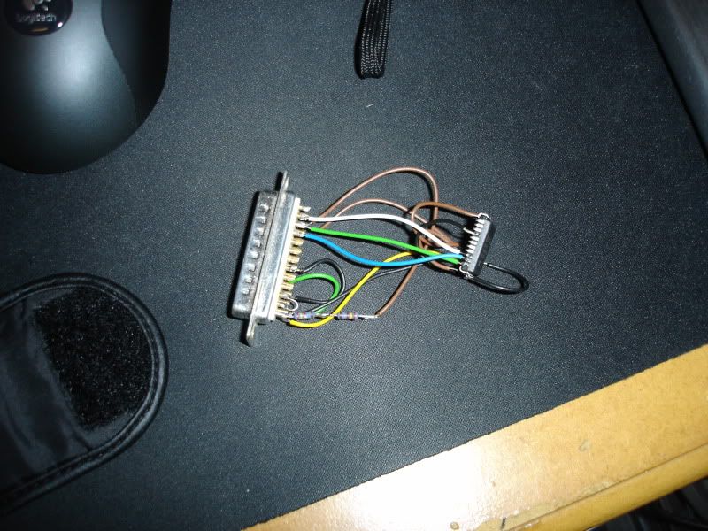
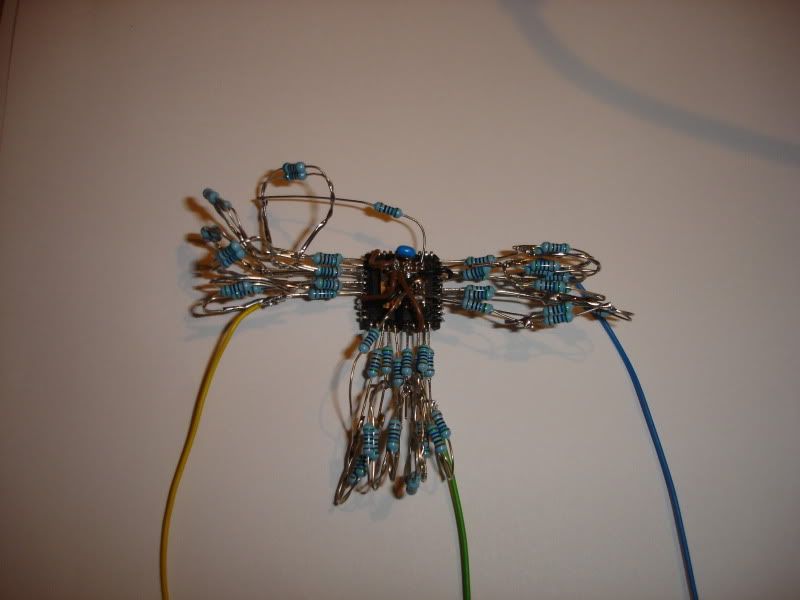
Got my diy programmer working after a few tweaks so went on with it, like I said though it was going to be built more less the same as it was on that page. Also, never again. Getting 60 resistors into such a small space is not fun :(. Anyway, pictures.

Programmer with cpld hooked to it
Programmer.jpg


First lot of resistors on

resistors.jpg


Finished.
DAC.jpg


The horror, resistors everywhere :D

Few look like they are touching, but it's just camera flash, none are touching where they are not meant to be.

Just gotta fit it to a n64 and hope it works rather than blowing up :D.
 
  • Like
Reactions: 1 person

alphamule

Well-Known Member
Member
Joined
Oct 24, 2011
Messages
429
Trophies
0
XP
184
Country
United States
That looks horrible, LOL!

You know that they have ICs for resistor arrays and not just transistorized circuits, right? Wish I had thought to mention it. You can get a single package with several resistors. Some come with common ground (B='buss') and others are separate (I='independant'). You obviously seem to have figured out that you don't need a board. Before people used custom-printed circuit boards or generic pre-drilled boards with lines set up for DIPs, there were people using something like a glue gun or temporary staging wire (AKA twist ties) to hold a chip in place while using a wire-wrap tool (read: small pliers or tweezers work) to run short wires between contacts and then remove the staging wire if used. You can solder that way, as well once all the connections are done because they provide a nice mechanical stability until you have a more permanent connection between them.

The fire hazard is a good reason that no one uses a glue gun/epoxy and cardboard/wood backing for circuits anymore. You can still use it to get the circuit layed out correctly and then remove the backing.
 

raulpica

With your drill, thrust to the sky!
Former Staff
Joined
Oct 23, 2007
Messages
11,056
Trophies
0
Location
PowerLevel: 9001
XP
5,716
Country
Italy
Got any links to your DIY programmer? (I hope it does EPROMs too! :P)

Anyway, it seems like I was late to the party, but I was going to suggest using the SMD components you found on eBay with a solid core wire on both sides. Oh well! :P
 

Armadillo

Well-Known Member
OP
Member
Joined
Aug 28, 2003
Messages
4,278
Trophies
3
XP
5,254
Country
United Kingdom
That looks horrible, LOL!

You know that they have ICs for resistor arrays and not just transistorized circuits, right? Wish I had thought to mention it. You can get a single package with several resistors. Some come with common ground (B='buss') and others are separate (I='independant'). You obviously seem to have figured out that you don't need a board. Before people used custom-printed circuit boards or generic pre-drilled boards with lines set up for DIPs, there were people using something like a glue gun or temporary staging wire (AKA twist ties) to hold a chip in place while using a wire-wrap tool (read: small pliers or tweezers work) to run short wires between contacts and then remove the staging wire if used. You can solder that way, as well once all the connections are done because they provide a nice mechanical stability until you have a more permanent connection between them.

The fire hazard is a good reason that no one uses a glue gun/epoxy and cardboard/wood backing for circuits anymore. You can still use it to get the circuit layed out correctly and then remove the backing.

Well 60 resistors hanging off the side of an ic was never going to be a work of art :D and yes, I have seen the resistor arrays. I had no idea how I would go about mounting them, other than a pcb, which as I said before would cost too much (may as well tracked down a rgb modable ntsc machine, once I buy materials for making board). Never heard or even seen the method you describe, that would have been nice as I could have done it that way, then removed the card or found a more permanent non conductive/flammable board to keep it on. Never built something that way either, always been either a pcb or some variation of stripboard or just together as this is, so would have been something new to learn/try :).


Got any links to your DIY programmer? (I hope it does EPROMs too! :P)

Anyway, it seems like I was late to the party, but I was going to suggest using the SMD components you found on eBay with a solid core wire on both sides. Oh well! :P

It was this http://www.digitalan...jtagpassme.jpg. Pretty sure it's just for programming Xilinx cplds. As for SMD resistors, think I would have passed on that. They are fiddly and annoying even when putting them on a board, couldn't deal with getting them in there with little links of wire.
 

raulpica

With your drill, thrust to the sky!
Former Staff
Joined
Oct 23, 2007
Messages
11,056
Trophies
0
Location
PowerLevel: 9001
XP
5,716
Country
Italy
Got any links to your DIY programmer? (I hope it does EPROMs too! :P)

Anyway, it seems like I was late to the party, but I was going to suggest using the SMD components you found on eBay with a solid core wire on both sides. Oh well! :P
It was this http://www.digitalan...jtagpassme.jpg. Pretty sure it's just for programming Xilinx cplds. As for SMD resistors, think I would have passed on that. They are fiddly and annoying even when putting them on a board, couldn't deal with getting them in there with little links of wire.
Funny, the pic doesn't open :/ It says 404 - not found.

Anyway, yeah, I hate having to fiddle with SMD resistors too, but sadly I haven't had to do with a drill-thru component in a while (except capacitors...) :P
 

Site & Scene News

Popular threads in this forum

General chit-chat
Help Users
    Veho @ Veho: Le youtube face.