Hacking Question Find a short to Ground on Nintendo Switch Motherboard

ZetShock

Member
OP
Newcomer
Joined
Dec 14, 2017
Messages
15
Trophies
0
Age
23
XP
136
Country
Germany
So its been a while since I last posted something similar, and I have yet again to return to this forum about a repair question for a Switch I am currently repairing for a relative.

Anyways, the consoler does not turn on nor does it give any signs of life off of it. Plugging in the battery or a charging cable results in a faint high pitched noise from the mainboard (that usually can be heard when the console is fully functional and running), which suggests the motherboard does receive power. As it appears to be, after comparing the motherboard of a functional Switch against this one, is that on the faulty board, a 1,8V power line is shorted to Ground through a component that I am trying to find. Powering that 1.8V rail with a lab bench power supply results that on the faulty board around 0.4 Amps of power is running through the rail to ground, and measuring the resistance between that power rail to ground shows that we only have a resistance of about 3,4Ω between those lines.

When calculating the wattage that this power loss is occuring at, we get around 0.7 Watts of power loss, which is barely heating up the component that is shorted, yet because of the short of those two rails the processor, and all caps/resistors that are near the processor on the opposite side of the board dont get the full 1,8 Volts they are supposed to get, hence why the console does not turn on or do anything at all.

Since we are dealing with a short here, one could assume that the area of the short heats up, but using the freeze spray or alcohol method to see what area evaporates first did not bring any results, as about 1 Watt of power loss in that area is not providing enough noticeable heat. So, since we cannot use heat to find the fault, how else could I possibly find a short? I have known locations where to measure the 1,8V lines, but as well all know we cant accurately measure if a component is shorted while it is still soldered into place.

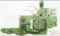
I have attached a cutout of the back of the mainboard where the short is most likely to be.

Now, I know this is not a technicians forum, but perhaps one of you guys might have an idea. And of course, feel free to ask me any questions regarding the motherboard or what Ive tried already.

Thanks in advance!
 

Attachments

  • Screenshot_4.png
    Screenshot_4.png
    120.2 KB · Views: 3,301

Kerbangman

Well-Known Member
Member
Joined
Sep 19, 2016
Messages
525
Trophies
0
Age
61
XP
690
Country
Thats a hard one to sort without taking components off.

I would first check for ESD protection devices on the rail.
Possible static attack and a TVS etc pulling the reg down.

Check the regs by lifting the output pin to see if the rail lifts.

Ceramic caps tend to be reliable.
 

JacksonS

Well-Known Member
Member
Joined
Feb 13, 2016
Messages
427
Trophies
0
XP
1,232
Country
United States
I doubt there's just a random passive component causing a short to ground. The IC that produces 1.8V is likely damaged and needs to be replaced, or any other ICs that interface directly with the 1.8V rail.
 

linkinworm

Well-Known Member
Member
Joined
May 30, 2008
Messages
1,597
Trophies
1
Age
33
Location
Birmingham (England)
XP
1,968
Country
you really want to just buy a multimeter and find it properly, you cant just guess this stuff, everything leads to somewhere and you can find the component causing the issue fairly quickly, even a cheap one that just beeps might be enough to just find thing out, ideally you get one that can at least tell if something is drawing too much voltage or not enough voltage when it should be
 

snam11

Well-Known Member
Member
Joined
Jan 10, 2007
Messages
108
Trophies
1
XP
1,130
Country
United States
well, i would use the simplest way to check if one of the caps is shorted: with a multimeter with the continuity mode (or if yours have it, set it with the "beep" sound on), use the probes on both sides of the cap.
if you hear a sound, the cap is shorted and needs to be replaced. If all the caps are ok, i'm out of clues
 
  • Like
Reactions: Rauliki

FAST6191

Techromancer
Editorial Team
Joined
Nov 21, 2005
Messages
36,798
Trophies
3
XP
28,311
Country
United Kingdom
What is with the spam and dumb cunt responses? Do we want another 3ds or wii section? It will happen again if you all drive off people with genuine questions. There are doubtless places on the internet with a higher proportion of fault finding types or relatively more active ones but it is hardly absent here (games, modding and such not being unknown hobbies among said electrical repair inclined types) and it is not a new phenomenon either.

That picture I can't do much with as it is far too low res -- it is possible to do with a camera but microscope or loupe is what I would have to play with. Nothing there looks obviously misaligned, badly placed or big solder blob shorted but at the sizes and lack of res there I am very far from any kind of certainty.
Compared to the switch teardown on
https://www.ifixit.com/Teardown/Nintendo+Switch+Teardown/78263
You appear to be missing a component in line with the top of Z in the stamped alphanumeric bit. Whether that is a simple hardware revision or not I do not know but I mention it anyway. Can't tell what it is on that but a little black band device could well be a power supply of some form and thus causing a low voltage in that location in its absence. Picture is too low res to see if it was a mechanical removal or something, not that a bad day with the paste dispenser would show even then.

Anyway I assume no thermal camera -- 0.7 watts is not a lot (might even struggle with fingers outside of a known fault/common fault scenario) but most surface mount components are rated for less than half that (maybe even a quarter that) and will thus cause them to light up rather brightly under said thing. IR thermometer might do too but it will take longer. I should also say it is not impossible that initial current draw is rather high (it is an underclocked shield after all, if said clocks or multipliers thereof are software set...) and it is then reduced by whatever means, if the thing is stuck in a boot loop and can not get to the current drop part then this may be a red herring. If you have a known working reference then that might be worth testing against.

Cowboy method. Fly a voltage lead to different points in the chain to narrow the fault down further. Normally better to save that for open circuit faults but can do things here. If you want to create more work you can also try breaking ground connections and providing them back.

Have you tried light pressure on/flexing of the board? For these multi layer monstrosities then it can tell you a surprising amount.
 

Rauliki

Well-Known Member
Member
Joined
Oct 24, 2016
Messages
134
Trophies
0
Age
47
XP
205
Country
Poland
So its been a while since I last posted something similar, and I have yet again to return to this forum about a repair question for a Switch I am currently repairing for a relative.

Anyways, the consoler does not turn on nor does it give any signs of life off of it. Plugging in the battery or a charging cable results in a faint high pitched noise from the mainboard (that usually can be heard when the console is fully functional and running), which suggests the motherboard does receive power. As it appears to be, after comparing the motherboard of a functional Switch against this one, is that on the faulty board, a 1,8V power line is shorted to Ground through a component that I am trying to find. Powering that 1.8V rail with a lab bench power supply results that on the faulty board around 0.4 Amps of power is running through the rail to ground, and measuring the resistance between that power rail to ground shows that we only have a resistance of about 3,4Ω between those lines.

When calculating the wattage that this power loss is occuring at, we get around 0.7 Watts of power loss, which is barely heating up the component that is shorted, yet because of the short of those two rails the processor, and all caps/resistors that are near the processor on the opposite side of the board dont get the full 1,8 Volts they are supposed to get, hence why the console does not turn on or do anything at all.

Since we are dealing with a short here, one could assume that the area of the short heats up, but using the freeze spray or alcohol method to see what area evaporates first did not bring any results, as about 1 Watt of power loss in that area is not providing enough noticeable heat. So, since we cannot use heat to find the fault, how else could I possibly find a short? I have known locations where to measure the 1,8V lines, but as well all know we cant accurately measure if a component is shorted while it is still soldered into place.


Thanks in advance!
If you have a working switch board you can measure all resistance, check capacitors, voltage and compare.
 

FAST6191

Techromancer
Editorial Team
Joined
Nov 21, 2005
Messages
36,798
Trophies
3
XP
28,311
Country
United Kingdom
If you have a working switch board you can measure all resistance, check capacitors, voltage and compare.
Measuring things in circuit is tricky, as the OP mentioned. Or if you prefer
https://xkcd.com/356/
Even with a reference the rest of the system may be different enough to really mess your readings up. Good enough for checking for a dead short or for something gone open/several orders of magnitude different.

You can desolder one leg but that is a lot of work, or maybe do something with high frequency if you have it but then you have to interpret it.
 
  • Like
Reactions: Borega

BvanBart

Gaming addict #2 and some
Member
Joined
Apr 16, 2007
Messages
1,315
Trophies
1
Age
36
Location
Bikini Bottom
XP
1,466
Country
Netherlands
This is so interesting to follow! I use a very inconvenient way to see if there is a short... us an LED.
When connecting the pins between the LED it should light up.
 

ZetShock

Member
OP
Newcomer
Joined
Dec 14, 2017
Messages
15
Trophies
0
Age
23
XP
136
Country
Germany
well, i would use the simplest way to check if one of the caps is shorted: with a multimeter with the continuity mode (or if yours have it, set it with the "beep" sound on), use the probes on both sides of the cap.
if you hear a sound, the cap is shorted and needs to be replaced. If all the caps are ok, i'm out of clues

The problem is that when measuring any cap on that power rail you always hear beeping, because you cannot know whether the short is across the cap you are measuring on or if it is across somewhere else, and the cap you are measuring on is connected to that shorted component.

Tried that already, but thanks anyways!

--------------------- MERGED ---------------------------

Measuring things in circuit is tricky, as the OP mentioned. Or if you prefer
https://xkcd.com/356/
Even with a reference the rest of the system may be different enough to really mess your readings up. Good enough for checking for a dead short or for something gone open/several orders of magnitude different.

You can desolder one leg but that is a lot of work, or maybe do something with high frequency if you have it but then you have to interpret it.

Of course it is always possible to desolder all of the components on the back, but they are extremely tiny, and even though I can do micro soldering it would be alot of work. Dont have an oscilloscope, so cant interpret any signals :/
 

ZetShock

Member
OP
Newcomer
Joined
Dec 14, 2017
Messages
15
Trophies
0
Age
23
XP
136
Country
Germany
What is with the spam and dumb cunt responses? Do we want another 3ds or wii section? It will happen again if you all drive off people with genuine questions. There are doubtless places on the internet with a higher proportion of fault finding types or relatively more active ones but it is hardly absent here (games, modding and such not being unknown hobbies among said electrical repair inclined types) and it is not a new phenomenon either.

That picture I can't do much with as it is far too low res -- it is possible to do with a camera but microscope or loupe is what I would have to play with. Nothing there looks obviously misaligned, badly placed or big solder blob shorted but at the sizes and lack of res there I am very far from any kind of certainty.
Compared to the switch teardown on
https://www.ifixit.com/Teardown/Nintendo+Switch+Teardown/78263
You appear to be missing a component in line with the top of Z in the stamped alphanumeric bit. Whether that is a simple hardware revision or not I do not know but I mention it anyway. Can't tell what it is on that but a little black band device could well be a power supply of some form and thus causing a low voltage in that location in its absence. Picture is too low res to see if it was a mechanical removal or something, not that a bad day with the paste dispenser would show even then.

Anyway I assume no thermal camera -- 0.7 watts is not a lot (might even struggle with fingers outside of a known fault/common fault scenario) but most surface mount components are rated for less than half that (maybe even a quarter that) and will thus cause them to light up rather brightly under said thing. IR thermometer might do too but it will take longer. I should also say it is not impossible that initial current draw is rather high (it is an underclocked shield after all, if said clocks or multipliers thereof are software set...) and it is then reduced by whatever means, if the thing is stuck in a boot loop and can not get to the current drop part then this may be a red herring. If you have a known working reference then that might be worth testing against.

Cowboy method. Fly a voltage lead to different points in the chain to narrow the fault down further. Normally better to save that for open circuit faults but can do things here. If you want to create more work you can also try breaking ground connections and providing them back.

Have you tried light pressure on/flexing of the board? For these multi layer monstrosities then it can tell you a surprising amount.


Thanks for the detailed suggestions! Anyways, the picture I provided is a reference picture, and not from the board I have. If needed I could post higher resolution pictures of both motherboards from a working and the faulty console. Ill perhaps try flexing the board, but I do not believe that the short is caused by traces touching internally in the PCB. Breaking ground connections is something I could try, but again, we are dealing with lots of small components here, and hot air soldering them off and on one by one will probably break the board once I find the fault. Comparing a working board against this defective board visually, as well as any resistance/voltages did not give me many results so far, except that we know that I have a low resistance from a power line to ground, whereas on my working board I would get multiple thousands of ohms of resistance, so there definitely is something at fault here.

Ill inspect the board further, perhaps I can find anything interesting.
 

Selver

13,5,1,14,9,14,7,12,5,19,19
Member
Joined
Dec 22, 2015
Messages
219
Trophies
0
XP
426
Country
So its been a while since I last posted something similar, and I have yet again to return to this forum about a repair question for a Switch I am currently repairing for a relative.
Since the switch came out less than one year ago, and came with a 1 year warranty, it seems "obvious" to ask... why not have the unit repaired under warranty?

FAST6191 also mentioned something interesting:
... 0.7 watts ... it is not impossible that initial current draw is rather high ... and it is then reduced by whatever means, if the thing is stuck in a boot loop and can not get to the current drop part then this may be a red herring.

At the risk of asking the obvious, have you validated the connectivity of the system's eMMC daughterboard? If it's stuck in a boot loop, it may be unable to decrypt / validate the boot signatures needed, or perhaps doesn't even see the eMMC device at all?
 

LineoftheDead

Well-Known Member
Newcomer
Joined
Oct 24, 2015
Messages
84
Trophies
0
Age
33
XP
216
Country
United States
Thanks for the detailed suggestions! Anyways, the picture I provided is a reference picture, and not from the board I have. If needed I could post higher resolution pictures of both motherboards from a working and the faulty console. Ill perhaps try flexing the board, but I do not believe that the short is caused by traces touching internally in the PCB. Breaking ground connections is something I could try, but again, we are dealing with lots of small components here, and hot air soldering them off and on one by one will probably break the board once I find the fault. Comparing a working board against this defective board visually, as well as any resistance/voltages did not give me many results so far, except that we know that I have a low resistance from a power line to ground, whereas on my working board I would get multiple thousands of ohms of resistance, so there definitely is something at fault here.

Ill inspect the board further, perhaps I can find anything interesting.
welcome back dude - you mentioned 3 - 4 ohms to ground and a probable short, when testing a good unit, what ohm reading do you get?

the only reason I ask is because I was banging my head against a wall for a similar situation with yet another product (not a switch). 1.8v rail went to +1.8v rail via jumper. component just before +1.8v rail was boiling hot. clearing jumper stops that from boiling. checking +1.8v with jumper removed shows little resistance to ground (this rail goes to video chip). I removed every component on +1.8v rail (most of them are 0 ohm resistors and only one way to ground via capacitor (which tested OK)), but no change in ohms. I then moved backwards, the IC that was getting hot was receiving 3 volts on input and sending 3 volts to output pin. 3 components before this IC is a voltage divider, (like a series of resistors). this voltage divider should be taking 3 volts and changing that to 1.8 volts.

I did solder a wire directly to ground and to +1.8v but nothing had gotten hot... probing verified voltage was correct.... voltage divider is the issue, unit was being supplied 3 volts on a 1.8 volt rail

I guess what im getting at is.... you might not have a short to ground. test voltage to ground on both units and report back. look up any part numbers you can find on IC's and test both input and output pins
 

ZetShock

Member
OP
Newcomer
Joined
Dec 14, 2017
Messages
15
Trophies
0
Age
23
XP
136
Country
Germany
Since the switch came out less than one year ago, and came with a 1 year warranty, it seems "obvious" to ask... why not have the unit repaired under warranty?

I received the switch for repair, it has already been opened before so it does not have any warranty anymore

FAST6191 also mentioned something interesting:


At the risk of asking the obvious, have you validated the connectivity of the system's eMMC daughterboard? If it's stuck in a boot loop, it may be unable to decrypt / validate the boot signatures needed, or perhaps doesn't even see the eMMC device at all?

I did not yet, but that would not explain why there is a low resistance on the faulty board whereas there is a high resistance on the working board between the power rail and ground

--------------------- MERGED ---------------------------

maybe try the alcohol method to locate the shorted/bad component?
I even tried freeze spray, but the little current that is running through the short is barely heating up anything. Ill give that another try, but I doubt it

--------------------- MERGED ---------------------------

welcome back dude - you mentioned 3 - 4 ohms to ground and a probable short, when testing a good unit, what ohm reading do you get?

the only reason I ask is because I was banging my head against a wall for a similar situation with yet another product (not a switch). 1.8v rail went to +1.8v rail via jumper. component just before +1.8v rail was boiling hot. clearing jumper stops that from boiling. checking +1.8v with jumper removed shows little resistance to ground (this rail goes to video chip). I removed every component on +1.8v rail (most of them are 0 ohm resistors and only one way to ground via capacitor (which tested OK)), but no change in ohms. I then moved backwards, the IC that was getting hot was receiving 3 volts on input and sending 3 volts to output pin. 3 components before this IC is a voltage divider, (like a series of resistors). this voltage divider should be taking 3 volts and changing that to 1.8 volts.

I did solder a wire directly to ground and to +1.8v but nothing had gotten hot... probing verified voltage was correct.... voltage divider is the issue, unit was being supplied 3 volts on a 1.8 volt rail

I guess what im getting at is.... you might not have a short to ground. test voltage to ground on both units and report back. look up any part numbers you can find on IC's and test both input and output pins


Great to see you on here again! Right, so it would make sense to find the area where these 1,8v are being made, which is probably through a voltage divider as you said. Some ICs I could find datasheets for barely show any information as to what pin is supposed to receive what voltage, but I do have a couple of locations that I could check if any measurements exceed the maximum rated voltage for that component. I will measure the resistance between the rails on the working board later today and post an update.

Also, since I recently got myself a lab bench power supply, and if the problem is indeed a component shorting something to ground, I could hook up the power supply to the 1,8v rail and ground to see how many amps are flowing. In fact, I tried this before to heat up the area that was causing the short and to find it with the alcohol method, but the produced heat was just to little to be noticeable. Though, increasing the voltage on the power supply above 1,8v to heat up and identify the faulty component easier should in theory work, right? If we are dealing with a short here a higher voltage should not damage any other components on that rail that are perhaps only rated for a max of 1,8v because the power is running through the short. Im just afraid to burn any traces on the pcb, so perhaps this is only the last thing I should try before everything else.
 

LineoftheDead

Well-Known Member
Newcomer
Joined
Oct 24, 2015
Messages
84
Trophies
0
Age
33
XP
216
Country
United States
I did not yet, but that would not explain why there is a low resistance on the faulty board whereas there is a high resistance on the working board between the power rail and ground

--------------------- MERGED ---------------------------


I even tried freeze spray, but the little current that is running through the short is barely heating up anything. Ill give that another try, but I doubt it

--------------------- MERGED ---------------------------


Great to see you on here again! Right, so it would make sense to find the area where these 1,8v are being made, which is probably through a voltage divider as you said. Some ICs I could find datasheets for barely show any information as to what pin is supposed to receive what voltage, but I do have a couple of locations that I could check if any measurements exceed the maximum rated voltage for that component. I will measure the resistance between the rails on the working board later today and post an update.

Also, since I recently got myself a lab bench power supply, and if the problem is indeed a component shorting something to ground, I could hook up the power supply to the 1,8v rail and ground to see how many amps are flowing. In fact, I tried this before to heat up the area that was causing the short and to find it with the alcohol method, but the produced heat was just to little to be noticeable. Though, increasing the voltage on the power supply above 1,8v to heat up and identify the faulty component easier should in theory work, right? If we are dealing with a short here a higher voltage should not damage any other components on that rail that are perhaps only rated for a max of 1,8v because the power is running through the short. Im just afraid to burn any traces on the pcb, so perhaps this is only the last thing I should try before everything else.
be careful, its 1.8 for a reason, raise the voltage and you risk blowing the entire rail (what if you blow video?)
 

Site & Scene News

Popular threads in this forum

General chit-chat
Help Users
  • Psionic Roshambo @ Psionic Roshambo:
    So my opinion is that they could age a bit better in the future, and maybe AMD will continue improving them via drivers like they tend to do. No guarantee there but they have done it in the past. Just a feeling I have.
  • The Real Jdbye @ The Real Jdbye:
    cyberpunk at 4k without DLSS/fidelityfx *might* exceed 12gb
    +1
  • The Real Jdbye @ The Real Jdbye:
    but that game barely runs at native 4k
  • Psionic Roshambo @ Psionic Roshambo:
    I think it was some newer games and probably poorly optimized PS4 or PS5 ports
  • The Real Jdbye @ The Real Jdbye:
    they definitely will age better but i feel dlss might outweigh that since it looks about as good as native resolution and much less demanding
    +1
  • Psionic Roshambo @ Psionic Roshambo:
    When I played Cyberpunk on my old 2080 Ti it sucked lol
  • The Real Jdbye @ The Real Jdbye:
    AMD could introduce something comparable to DLSS but nvidia's got a lot more experience with that
  • The Real Jdbye @ The Real Jdbye:
    least amd 7xxx has tensor cores which the previous generations didn't so there is the potential for AI upscaling
  • Psionic Roshambo @ Psionic Roshambo:
    They have FSR or whatever it's called and yeah it's still not great
  • The Real Jdbye @ The Real Jdbye:
    so AMD seem to finally be starting to take AI seriously
  • Psionic Roshambo @ Psionic Roshambo:
    Oh yeah those new 8000 CPUs have AI cores built in that's interesting
  • Psionic Roshambo @ Psionic Roshambo:
    Maybe they plan on offloading to the CPU?
  • Psionic Roshambo @ Psionic Roshambo:
    Would be kinda cool to have the CPU and GPU working in random more
  • Psionic Roshambo @ Psionic Roshambo:
    Tandem even
  • The Real Jdbye @ The Real Jdbye:
    i think i heard of that, it's a good idea, shouldn't need a dedicated GPU just to run a LLM or video upscaling
  • The Real Jdbye @ The Real Jdbye:
    even the nvidia shield tv has AI video upscaling
  • The Real Jdbye @ The Real Jdbye:
    LLMs can be run on cpu anyway but it's quite slow
  • BakerMan @ BakerMan:
    Have you ever been beaten by a wet spaghetti noodle by your girlfriend because she has a twin sister, and you got confused and fucked her dad?
  • Psionic Roshambo @ Psionic Roshambo:
    I had a girlfriend who had a twin sister and they would mess with me constantly.... Until one chipped a tooth then finally I could tell them apart.... Lol
  • Psionic Roshambo @ Psionic Roshambo:
    They would have the same hair style the same clothes everything... Really messed with my head lol
  • Psionic Roshambo @ Psionic Roshambo:
    @The Real Jdbye, I could see AMD trying to pull off the CPU GPU tandem thing, would be a way to maybe close the gap a bit with Nvidia. Plus it would kinda put Nvidia at a future disadvantage since Nvidia can't make X86/64 CPUs? Intel and AMD licensing issues... I wonder how much that has held back innovation.
  • The Real Jdbye @ The Real Jdbye:
    i don't think nvidia wants to get in the x64 cpu market anyways
  • The Real Jdbye @ The Real Jdbye:
    you've seen how much intel is struggling getting into the gpu market
  • The Real Jdbye @ The Real Jdbye:
    and nvidia is already doing ARM
    The Real Jdbye @ The Real Jdbye: and nvidia is already doing ARM