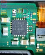
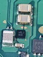
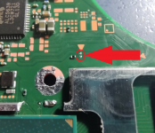
Hardware Components used on the Switch (mostly the motherboard and main console)

otaconn23

Active Member
Newcomer
Joined
Aug 16, 2020
Messages
29
Trophies
0
Age
113
XP
94
Country
United States
3. check if console in RCM automatically from cold start.
you were right! it was stuck on AutoRCM. thank you :D
Keep us updated on what you find.
maybe the same applies for your situation? Since M92 and BQ24 caps showed no short, I just confirmed USB was ok and then tried injecting with TegraRCM.
to confirm USB, unplug BATT, plugged in charger, checked BATT leads on board to confirm 4-5v.
 
  • Like
Reactions: White_Raven_X

ewabc886

Well-Known Member
Newcomer
Joined
Jul 11, 2018
Messages
84
Trophies
0
XP
392
Country
Hong Kong
View attachment 171085 Yay! Found the thread!

Can we make a TinySoldering™️ meme? ;)

Thank fook I`m second poster!

Right... Heres something to get you going... @WadsRUs

EDIT: 24.06.19 Correction of BQ24193 47nF cap
Hello,
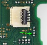
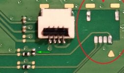
I would like to know the resistor value pointed by light blue arrow in the picture (Fig.1).
The board I'm dealing with is really messed up by the last owner at the same resistor (Fig.2).
I guess he was trying to solder the trinket M0
It booted OFW normally, and cannot boot into CFW due to broken SD connector.
After cleaning the pad (Fig.1), the board doesn't boot OFW normally and stuck at the Switch logo.

anyway, now the Vol +/- buttons are not functioning, power button is fine.
I would like to ask about the resistor value, and hoping to repair the vol+ button
Also, is the red line a correct jump in Fig.1? I would like to do the jump since the pad is totally gone already.

Resistor_Fig.1.jpg

Resistor_Fig.2.JPG
 

jkyoho

Well-Known Member
Member
Joined
Sep 2, 2020
Messages
1,270
Trophies
0
Age
39
Location
TORONTO
Website
form.jotform.com
XP
2,201
Country
Canada
Hello,
I would like to know the resistor value pointed by light blue arrow in the picture (Fig.1).
The board I'm dealing with is really messed up by the last owner at the same resistor (Fig.2).
I guess he was trying to solder the trinket M0
It booted OFW normally, and cannot boot into CFW due to broken SD connector.
After cleaning the pad (Fig.1), the board doesn't boot OFW normally and stuck at the Switch logo.

anyway, now the Vol +/- buttons are not functioning, power button is fine.
I would like to ask about the resistor value, and hoping to repair the vol+ button
Also, is the red line a correct jump in Fig.1? I would like to do the jump since the pad is totally gone already.

View attachment 279755
View attachment 279756
RESISTOR is 150 ohm. And yes .jumper path is correct
 
  • Like
Reactions: ewabc886

Aylo

Member
Newcomer
Joined
Sep 24, 2019
Messages
8
Trophies
0
Age
37
XP
65
Country
United Kingdom
View attachment 171085 Yay! Found the thread!

Can we make a TinySoldering™️ meme? ;)

Thank fook I`m second poster!

Right... Heres something to get you going... @WadsRUs

EDIT: 24.06.19 Correction of BQ24193 47nF cap
Just wanted to add my two cents to this, someone might find this helpful.
I have a HAC-CPU-20 board and the resistor values are very different to the ones in this picture.

The picture lists all resistors down by the BQ24193 IC as being 10k ohm 0201.

On closer inspection I've found the following values on a HAC-CPU-20 board that works perfectly fine.

hopefully someone who needs this will find it useful.
 

Attachments

  • WIN_20211015_10_16_54_Pro.jpg
    WIN_20211015_10_16_54_Pro.jpg
    664.5 KB · Views: 130

ewabc886

Well-Known Member
Newcomer
Joined
Jul 11, 2018
Messages
84
Trophies
0
XP
392
Country
Hong Kong
Just wanted to add my two cents to this, someone might find this helpful.
I have a HAC-CPU-20 board and the resistor values are very different to the ones in this picture.

The picture lists all resistors down by the BQ24193 IC as being 10k ohm 0201.

On closer inspection I've found the following values on a HAC-CPU-20 board that works perfectly fine.

hopefully someone who needs this will find it useful.
That's interesting to see a 0Ohm
 

Ottoclav

Well-Known Member
Member
Joined
May 27, 2020
Messages
132
Trophies
0
Age
43
XP
290
Country
United States
Yeah, it read 0.1ohm on my multimeter so I assumed it was a 0Ohm.

I've seen a few of them before on Xbox one S parts, but they're not all that common I dont think.
In the industry I work in, they are usually used for splicing where replacing a wire modification would take too much time and effort than would be allowed. snip the wire, bond a 0ohm resistor to the board, and continue with the modification. This is usually with long lengths of wire, normally enamel coated.
 
  • Like
Reactions: Aylo

Ottoclav

Well-Known Member
Member
Joined
May 27, 2020
Messages
132
Trophies
0
Age
43
XP
290
Country
United States
Does anyone have photos of the Mainboards that aren't marked up and haven't been worked on at all? I'm trying to compare the two I have with fresh boards, but most of the photos I can find are too blurry, or have been marked up with drawings. I have both HAC-CPU-10 and a HAC-CPU-20 mainboards and need some comparative photos of both sides for each.
 

Aylo

Member
Newcomer
Joined
Sep 24, 2019
Messages
8
Trophies
0
Age
37
XP
65
Country
United Kingdom
Does anyone have photos of the Mainboards that aren't marked up and haven't been worked on at all? I'm trying to compare the two I have with fresh boards, but most of the photos I can find are too blurry, or have been marked up with drawings. I have both HAC-CPU-10 and a HAC-CPU-20 mainboards and need some comparative photos of both sides for each.
I have a HAC-CPU-20 that hasnt had any work, are you looking for a particular side/section of the board?
 

Ottoclav

Well-Known Member
Member
Joined
May 27, 2020
Messages
132
Trophies
0
Age
43
XP
290
Country
United States
I have a HAC-CPU-20 that hasnt had any work, are you looking for a particular side/section of the board?
I'd like both sides, with the highest definition possible, so I can zoom in on different parts without any or least amount of pixelization. But whatever photos you have would be great, so I could make a collage or something if I need to.
 
Last edited by Ottoclav,

note9

Member
Newcomer
Joined
Sep 13, 2020
Messages
23
Trophies
0
Age
46
XP
161
Country
United Kingdom
anyone know the value of the black capacitor near the power button connector?

pic1 is normal switch and pic2 is switch lite left board.
 

Attachments

  • cap1.jpg
    cap1.jpg
    42.1 KB · Views: 86
  • cap2.jpg
    cap2.jpg
    110.3 KB · Views: 82

Shinai7047

Member
Newcomer
Joined
May 23, 2021
Messages
7
Trophies
0
Age
30
XP
45
Country
United States
Molex 503480-0400 same as the backlight connector thanks to @WadsRUs not tested.


Or
Do you know if that connector can ALSO be used on the fan connector below it? They appear to be the same size and the mounting appears to be the same but wanted to ask before I go trying to use an improper replacement since I do not have a donor board.
 

jkyoho

Well-Known Member
Member
Joined
Sep 2, 2020
Messages
1,270
Trophies
0
Age
39
Location
TORONTO
Website
form.jotform.com
XP
2,201
Country
Canada
Do you know if that connector can ALSO be used on the fan connector below it? They appear to be the same size and the mounting appears to be the same but wanted to ask before I go trying to use an improper replacement since I do not have a donor board.
yes, backlight CNT and power CNT are interchangeable.
 

Modificatorul

Well-Known Member
Member
Joined
Oct 28, 2009
Messages
268
Trophies
1
XP
2,298
Country
Antarctica
Do you know if that connector can ALSO be used on the fan connector below it? They appear to be the same size and the mounting appears to be the same but wanted to ask before I go trying to use an improper replacement since I do not have a donor board.
Fan connector is jst 04FHS-RSM1-GAN-TB(LF) i already posted in his thread and tested.(only diference is the retention tab is black not grey)

https://www.ebay.co.uk/itm/10PCS-X-04FHS-RSM1-GAN-TB-LF-0-5mm-pitch-4Pin-JST-Connector-/332231390814
or
https://www.aliexpress.com/item/100...c2-1&pdp_ext_f={"sku_id":"12000022451939961"}


or same color more expensive

https://www.aliexpress.com/item/100...fd-0&pdp_ext_f={"sku_id":"12000024701006571"}

I don't think you can use the backlight/volume/power connector for fan.
 

Shinai7047

Member
Newcomer
Joined
May 23, 2021
Messages
7
Trophies
0
Age
30
XP
45
Country
United States
Fan connector is jst 04FHS-RSM1-GAN-TB(LF) i already posted in his thread and tested.(only diference is the retention tab is black not grey)


or


or same color more expensive


I don't think you can use the backlight/volume/power connector for fan.
Thanks for that! Saved me some time lol
 

Shinai7047

Member
Newcomer
Joined
May 23, 2021
Messages
7
Trophies
0
Age
30
XP
45
Country
United States
Fan connector is jst 04FHS-RSM1-GAN-TB(LF) i already posted in his thread and tested.(only diference is the retention tab is black not grey)

or


or same color more expensive


I don't think you can use the backlight/volume/power connector for fan.
So, I see continuity but again no fan spin. Do you know if these things have fan spin at power on / measurable voltage that I could probe for just to confirm 5v is good? As right now I don't think I see any when the switch is powered on.
 

Site & Scene News

Popular threads in this forum

General chit-chat
Help Users
    AncientBoi @ AncientBoi: yes? Interesting way to get Hi