Hi there!
I hope it's fine to post a separate thread apart from the noob questions one. But I think the problem is specific enough...
So I start from the beginning. I tried soldering in a modchip in my old nintendo switch.
As I used it the last time when BotW came out, I firstly made sure everything was working, so I tested a Game via Card, a SD Card, both of my Joycons and battery draining/loading over the course of a few hours.
Everything was working fine, so I started disassembling the poor thing. For my convenience, I stopped disassembly once I removed the silver backplate/shield and all Parts I needed were visible.
Only the Battery cable and eMMc chip did come off aswell, everything else did stay where it was.
My goal was firstly to put all required cables on the board, so both Data Pins, 3V and ground. Data pins were easy to solder on, ground was also fine. Power gave me a headache while only looking at it, so I took the alternative 3,3V pin mentioned in this thread (gbatemp.net/threads/internal-modchip-samd21-trinket-m0-gemma-m0-itsybitsy-m0-express-guide-files-support.508068/), showing 3.3V pins under the eMMc board(gbatemp.net/attachments/alternative3v-jpg.149057/).
(Sorry can't post links yet)
Now with everything soldered on, I took a last look under a magnifying glass if there are no unwanted connections, and I deemed it good enough.
I tried to start but the modchip did not turn on, I measured the Power on the chip and did not get 3.3V. Switch OS booted fine tho.
I put everything off the board, and resoldered every connection again.
Well and there I am, trying to start my Switch and getting greeted by a black screen. Modchip did indeed blink once or twice, but after that everything just seems to be turned off.
I tried to start the switch with my RCM Jig inserted and power+vol+ pressed while connected to my pc running tegraGui but it did not show up.
If I put it in the dock, the dock flashes green once, so I guess the port is working ? I tried putting my phone in the dock, but neither my phone, nor the dock did anything, so it seems the dock is still registering a switch tries to boot.
I tried to remove my workings in the switch by desoldering the modchip again.
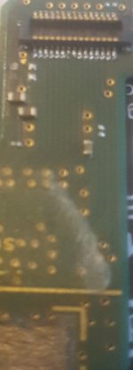
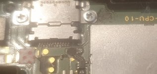
I see some things that might or might not be damage to the board. On the right USB pad, and the ground pad is some kinda "dirt" (?), which looks like sticky black powder.
Also are these two missing the actual golden pad where I did solder the cable on. I thought the golden pads were part of the underlying layer of the board so maybe it's just some kind of conductive material ?
I don't know, if I recall correctly (I'm 99% sure), these pads looked like that the first time i soldered the chip off again already and the switch did start peacefully.
What I tried so far:
-> Desoldering everything as mentioned above
-> Having the battery off the board for around half an hour
-> Putting the switch on the charger directly without the dock
-> Tried booting into RCM mode
-> Tried booting into emergency mode
-> Measured the voltage on the battery pad against the "maybe" broken ground port and got 3,3/3.6V
I tried to do some photos of the points mentioned, but I don't know if that's that helpful with the camera I have at hand...
Does anyone have an idea what could be tried else for this problem ? I don't really know what else I could do currently to resolve the issue.
Thanks in advance!
I hope it's fine to post a separate thread apart from the noob questions one. But I think the problem is specific enough...
So I start from the beginning. I tried soldering in a modchip in my old nintendo switch.
As I used it the last time when BotW came out, I firstly made sure everything was working, so I tested a Game via Card, a SD Card, both of my Joycons and battery draining/loading over the course of a few hours.
Everything was working fine, so I started disassembling the poor thing. For my convenience, I stopped disassembly once I removed the silver backplate/shield and all Parts I needed were visible.
Only the Battery cable and eMMc chip did come off aswell, everything else did stay where it was.
My goal was firstly to put all required cables on the board, so both Data Pins, 3V and ground. Data pins were easy to solder on, ground was also fine. Power gave me a headache while only looking at it, so I took the alternative 3,3V pin mentioned in this thread (gbatemp.net/threads/internal-modchip-samd21-trinket-m0-gemma-m0-itsybitsy-m0-express-guide-files-support.508068/), showing 3.3V pins under the eMMc board(gbatemp.net/attachments/alternative3v-jpg.149057/).
(Sorry can't post links yet)
Now with everything soldered on, I took a last look under a magnifying glass if there are no unwanted connections, and I deemed it good enough.
I tried to start but the modchip did not turn on, I measured the Power on the chip and did not get 3.3V. Switch OS booted fine tho.
I put everything off the board, and resoldered every connection again.
Well and there I am, trying to start my Switch and getting greeted by a black screen. Modchip did indeed blink once or twice, but after that everything just seems to be turned off.
I tried to start the switch with my RCM Jig inserted and power+vol+ pressed while connected to my pc running tegraGui but it did not show up.
If I put it in the dock, the dock flashes green once, so I guess the port is working ? I tried putting my phone in the dock, but neither my phone, nor the dock did anything, so it seems the dock is still registering a switch tries to boot.
I tried to remove my workings in the switch by desoldering the modchip again.
I see some things that might or might not be damage to the board. On the right USB pad, and the ground pad is some kinda "dirt" (?), which looks like sticky black powder.
Also are these two missing the actual golden pad where I did solder the cable on. I thought the golden pads were part of the underlying layer of the board so maybe it's just some kind of conductive material ?
I don't know, if I recall correctly (I'm 99% sure), these pads looked like that the first time i soldered the chip off again already and the switch did start peacefully.
What I tried so far:
-> Desoldering everything as mentioned above
-> Having the battery off the board for around half an hour
-> Putting the switch on the charger directly without the dock
-> Tried booting into RCM mode
-> Tried booting into emergency mode
-> Measured the voltage on the battery pad against the "maybe" broken ground port and got 3,3/3.6V
I tried to do some photos of the points mentioned, but I don't know if that's that helpful with the camera I have at hand...
Does anyone have an idea what could be tried else for this problem ? I don't really know what else I could do currently to resolve the issue.
Thanks in advance!