Hardware Any one have ninty switch mobo schematics ?

DaveLister

Well-Known Member
OP
Member
Joined
Apr 27, 2018
Messages
720
Trophies
0
Age
123
Location
lv426
XP
1,295
Country
Afghanistan
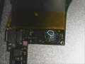
One of the broken switches i got, while working on the m92t36 chip, I noticed what looks like resistor , i could be wrong might be a cap was popped, both its sides had degraded and the center piece lives on. No issues with doing the repair on this part , i just cannot identify the needed part . It sits on two of the m92t36 ic traces. ?? Anyone know?

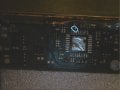
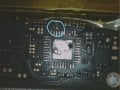
The pads have been re-prepped for the m92t36 , also i cleaned away the bad cap/resistor seen in image Still04. You can see in the images the part with no metal edges .

Anyone know the rating of this little part ? Still 6 shows something trailing or hanging out of its innards.

PS this is microscopic absolutely tiny - even when it sits on the tip of the pick up tool - you cannot see it . LOLS . In Still01 the 1 inch gaped lines you see are the space between the lines in my fingerprint on the tip of my finger . Help me Obey one , your my only hope.
 

Attachments

  • Still001.bmp
    5.5 MB · Views: 1,186
  • Still002.bmp
    5.5 MB · Views: 629
  • Still003.bmp
    5.5 MB · Views: 545
  • Still004.bmp
    5.5 MB · Views: 2,059
  • Still005.bmp
    5.5 MB · Views: 382
  • Still006.bmp
    5.5 MB · Views: 458
Last edited by DaveLister,
  • Like
Reactions: comput3rus3r

Man4

Member
Newcomer
Joined
Aug 25, 2018
Messages
7
Trophies
0
Age
49
XP
236
Country
Spain
Look like they are standard, anyway you can put any that fit on place with the same value even non smd. I think that can be a cap but, could you, please , do some more general picture for undertanding of what part of motherboard we talking about?, I saw the teardown pictures on ifixit and can't fit yours on the mainboard.

--------------------- MERGED ---------------------------

You can see mainboard pic here: The blue marked part i guest is the IC area you talking about: https://d3nevzfk7ii3be.cloudfront.net/igi/MvJEDTUnxMS4Olqs.huge
 

DaveLister

Well-Known Member
OP
Member
Joined
Apr 27, 2018
Messages
720
Trophies
0
Age
123
Location
lv426
XP
1,295
Country
Afghanistan
Order follows zoom inwards . Pic 1 for board orientation. Cheers if ya know the direction to point me .
 

Attachments

  • still1.jpg
    still1.jpg
    402.8 KB · Views: 720
  • still2.jpg
    still2.jpg
    233.7 KB · Views: 796
  • still3.jpg
    still3.jpg
    251.5 KB · Views: 1,257
  • still4.jpg
    still4.jpg
    397.5 KB · Views: 653

Razor83

Well-Known Member
Member
Joined
Dec 23, 2009
Messages
391
Trophies
1
XP
1,758
Country
The ROHM M92T36 used in the Switch appears to be very similar to the ROHM BM92T30MWV for which you can find the datasheet here:-
https://www.rohm.com/datasheet/BM92T30MWV/bm92t30mwv-e
Assuming I orientated your photos correctly to match this photo, then it should be a capacitor between VBUS ("VB" = Pin 9) and GND ("SGND" = Pin 8), and i'm guessing its 0402 size. As to the value, well your probably best using a capacitance meter to measure the value on another Switch.
 
Last edited by Razor83,

Man4

Member
Newcomer
Joined
Aug 25, 2018
Messages
7
Trophies
0
Age
49
XP
236
Country
Spain
Yes, Razor83, very good info, as we can see on the recomended schematic application seens to be 0,01 uF, anyway the best and safe way to solve it is that someone measure on other Switch to confirm like Razor83 told. Good luck!.
 

mattytrog

You don`t want to listen to anything I say.
Member
Joined
Apr 27, 2018
Messages
3,708
Trophies
0
Age
48
XP
4,328
Country
United Kingdom
The capacitor that is missing goes between VB and GND. Therefore it is used for smoothing / filtering. To smooth out the "high" voltage (20 odd volts) and to stop arcing within the chip when the power detector is switching between the different inputs so it seems. A bit like the old car ignotion points used to use to stop them pitting and arcing.

It is 0201 size... I normally fit 2.2uF there to be on the safe side.

Will Should get away with lower however.

--------------------- MERGED ---------------------------

i'm guessing its 0402 size.

No mate its 0201

:)
 
Last edited by mattytrog,

DaveLister

Well-Known Member
OP
Member
Joined
Apr 27, 2018
Messages
720
Trophies
0
Age
123
Location
lv426
XP
1,295
Country
Afghanistan
It's fukin tiny . Like tiny soldering guy would shit himself.
The capacitor that is missing goes between VB and GND. Therefore it is used for smoothing / filtering. To smooth out the "high" voltage (20 odd volts) and to stop arcing within the chip when the power detector is switching between the different inputs so it seems. A bit like the old car ignotion points used to use to stop them pitting and arcing.

It is 0201 size... I normally fit 2.2uF there to be on the safe side.

Will Should get away with lower however.

--------------------- MERGED ---------------------------


No mate its 0201

:)
I really didn't have much hope . You Sir are a legend . Would I need to buy a book of them ?. Sorry for the additional sourcing question where could I grab a few ?.

--------------------- MERGED ---------------------------

Yes, Razor83, very good info, as we can see on the recomended schematic application seens to be 0,01 uF, anyway the best and safe way to solve it is that someone measure on other Switch to confirm like Razor83 told. Good luck!.

Thanks for your help m8. Cheers.
 

mattytrog

You don`t want to listen to anything I say.
Member
Joined
Apr 27, 2018
Messages
3,708
Trophies
0
Age
48
XP
4,328
Country
United Kingdom
It's fukin tiny . Like tiny soldering guy would shit himself.

I really didn't have much hope . You Sir are a legend . Would I need to buy a book of them ?. Sorry for the additional sourcing question where could I grab a few ?.

--------------------- MERGED ---------------------------


Thanks for your help m8. Cheers.
Best bet would be RS components. Anything from about 100nF up should do same job.

Take one off something old. From what I see and in my past repairs, size isn't crucial
 
  • Like
Reactions: DaveLister

Razor83

Well-Known Member
Member
Joined
Dec 23, 2009
Messages
391
Trophies
1
XP
1,758
Country
The capacitor that is missing goes between VB and GND. Therefore it is used for smoothing / filtering. To smooth out the "high" voltage (20 odd volts) and to stop arcing within the chip when the power detector is switching between the different inputs so it seems. A bit like the old car ignotion points used to use to stop them pitting and arcing.

It is 0201 size... I normally fit 2.2uF there to be on the safe side.

Will Should get away with lower however.
Are you sure its 2.2uF? Looking at the application example on page 25 of the datasheet the recommended value between VB and SGND is 0.01uF. Most of the other capacitors to ground are 1uF, but this particular one is listed as 0.01uF (Thats one of the reasons why I thought it best to measure it if possible)

No mate its 0201

:)
Ah your right, I was guessing its size from the chip pin spacing (0.4mm) but got muddled up and forgot that SMD sizes are imperial not metric :wacko:
0201 is incredibly tiny! Good luck @DaveLister :)
 
Last edited by Razor83,

mattytrog

You don`t want to listen to anything I say.
Member
Joined
Apr 27, 2018
Messages
3,708
Trophies
0
Age
48
XP
4,328
Country
United Kingdom
In my experience, anything from 100nF up should do it. I must have skipped over that bit of the usage application notes

If it says 100nF, go for that. Just don't go any lower than that. Don't mistake nF for pF either!

The radio ham in me is coming out... /Shame

@DaveLister order a tape of 100 from RS

--------------------- MERGED ---------------------------

The best way to solder 0402 and lower, is to
  • clean both pads off with some braid
  • Get a sewing needle (30 gauge or thinner)
  • scratch it up so you get the chrome off and you are down to steel, or just make sure it is rough.
  • Tin it, solder component to the needle tip...
  • Build 1 pad up with a decent amount of solder... Place the pin-mounted component on there... Just touch the built-up solder side to join. Desolder the needle, repeat for other side.
  • Once both sides are tacked, give both sides a nice flow with some fluxite (do one at once or you will knock it off)
  • Final flow on both sides to make sure they are both attached. Clean flux off.

Make sure you only heat the component for literally a millisecond (or 10) or you will flow it right off.
 
Last edited by mattytrog,

DaveLister

Well-Known Member
OP
Member
Joined
Apr 27, 2018
Messages
720
Trophies
0
Age
123
Location
lv426
XP
1,295
Country
Afghanistan
Shit here was me thinking tacky flux would save the day lols. Thats much better way then the way i was going to approach it . Love the needle bit . detracting octo arm rig.

Edit i just bought 15W FM transmitter - a shit one , for shits n giggles , will up it to a FMuser FU-30a , only have a small area to cover .

Looking for a book of 4,000 or so with varying levels of capacitance - will need them again i would say .

--------------------- MERGED ---------------------------

Are you sure its 2.2uF? Looking at the application example on page 25 of the datasheet the recommended value between VB and SGND is 0.01uF. Most of the other capacitors to ground are 1uF, but this particular one is listed as 0.01uF (Thats one of the reasons why I thought it best to measure it if possible)


Ah your right, I was guessing its size from the chip pin spacing (0.4mm) but got muddled up and forgot that SMD sizes are imperial not metric :wacko:
0201 is incredibly tiny! Good luck @DaveLister :)
I aint afraid O no ghost.
Thanks - that pin trick will have me sorted - was going to sit with tacky and use tool to hold her down as i nipped both sides with iron . Tiny little prick for the win .

Did you ever just sit there proofing your posts and loose all reason thinking "Ghost" , or "the" is not spelled that way , its happening right now , I know over sharing .......
 
Last edited by DaveLister,

Site & Scene News

Popular threads in this forum

General chit-chat
Help Users
  • No one is chatting at the moment.
    Maximumbeans @ Maximumbeans: butte