


I have an SP ags-001 modded with backlight screen one of the new ones available on AliExpress. I have a new 850mah battery also AliExpress.what model you have, old or SP? im using a older NDS battery and red ligth on 30 min ....in any case, im waiting for a new NDS Battery for replace it
greetings
You are using an out of date browser. It may not display this or other websites correctly.
You should upgrade or use an alternative browser.
You should upgrade or use an alternative browser.
- Joined
- Jul 12, 2010
- Messages
- 162
- Trophies
- 1
- Age
- 36
- Location
- Bananna Land.
- Website
- www.nerdfy.com.br
- XP
- 835
- Country

My dears, and the brightness control? I know BennVenn used to have a very intelligent brightness controller, which used the three-button combination (U-Down-Start) as standard.
https://bennvenn.myshopify.com/prod...rightness-controller-for-gbc-and-gba-101-lcds
But with this product as sold out, is there any option, even indirect, to control the brightness of the screen?
or am I wrong, and even with the mod making direct connections on the battery, the Gameboy SP brightness button still works?
It may sound like bullshit, but I (and I know some guys) who have excessive sensitivity to white light from LCD screens in very dark environments.
Last edited by Mr Skinner,
My dears, and the brightness control? I know BennVenn used to have a very intelligent brightness controller, which used the three-button combination (U-Down-Start) as standard.
https://bennvenn.myshopify.com/prod...rightness-controller-for-gbc-and-gba-101-lcds
But with this product as sold out, is there any option, even indirect, to control the brightness of the screen?
or am I wrong, and even with the mod making direct connections on the battery, the Gameboy SP brightness button still works?
It may sound like bullshit, but I (and I know some guys) who have excessive sensitivity to white light from LCD screens in very dark environments.
In the mod i did the brightness button works and switches between full and around half brightness.
- Joined
- Jul 12, 2010
- Messages
- 162
- Trophies
- 1
- Age
- 36
- Location
- Bananna Land.
- Website
- www.nerdfy.com.br
- XP
- 835
- Country
Could you send me some reference material? I intend to make this my holiday project. =)In the mod i did the brightness button works and switches between full and around half brightness.
Carefully read through all the posts in this thread and you will work it out. That's what I did. All the info is there.Could you send me some reference material? I intend to make this my holiday project. =)
Hi.
I've used the help here to mod an old gba sp. All went well until I had to solder the wire from the GND pin on the converter to the motherboard.
Unfortunately I failed to realise that the square panel that you solder on to was covered in a protective insulation layer. My solder has bled between the pins of the adjacent CPU.
Now I am struggling to remove the solder.
Does anyone have any suggestions to help?
Or am I better off investing in another GBA SP to get a fresh motherboard?
Any help gratefully received.
By the way, the screen comes on when the GBA is turned on and seems to work brilliantly. Shame ghetto device can't play and cartridges at the moment.
Last edited by Timbob397,


Hey! I wanted to try this mod. As it required cutting a trace on the board, I did it. But since I bought the voltage regulator from Bennvenn, his mod doesn't require to cut a trace (which I already did). I was wondering if the fact that I cut the trace will affect in any way the mod if I continue with the Bennvenn's voltage regulator? Should I just continue the mod with all the wiring ? Thank you ")
PS: Here's a video on how to do the mod with the voltage regulator + the brightness controller
EDIT : Bennvenn's answered me. It doesn't matter if the trace have been cut or not as long as I'm following his guide
PS: Here's a video on how to do the mod with the voltage regulator + the brightness controller
EDIT : Bennvenn's answered me. It doesn't matter if the trace have been cut or not as long as I'm following his guide
Last edited by Orphae_Oreki,
I've been thinking about doing this mod, and I've found this thread to be very useful (so thanks to everyone who has contributed)! That said, I worked in manufacturing, building high-end ribbon microphones by hand for a few years, so I've got pretty good soldering skills. With that knowledge, I'd like to address some earlier posts here, as I often see bad advice given when it comes to soldering.
First off, most soldering is pretty easy. I don't mean that there isn't any skill in it; there is, especially when you actually do get into very small/difficult jobs. If you're struggling, don't get discouraged. Part of your struggle is probably inexperience (we all have to learn to get past that), but another large part of it could very well be your tooling. From my experience, soldering difficulty comes from tooling as opposed to experience much more than many other forms of manufacturing / handy work. If you really are struggling, consider looking into upgrading your tooling, as it might not be sufficient for the job.
Here is some tooling and technique advice I can give:
I'll start with a big one that I often see people talking about incorrectly: There is NO SUCH THING as having an iron that is too powerful for a job. Any iron worth using for jobs like this will have some form of temperature control, and that's what matters. You may not be able to control that temperature without changing tips (more on that later), but the iron will have a target temperature, and stay as close to it as possible. The most important part of a soldering iron is how efficiently it can deliver iron to its tip. When you solder, heat is pulled away from the iron, so it needs to be able keep up with how fast that pulling of heat is occurring. The more power you have available, the more heat you can pull from your tip before you start running into issues. This is not only important when soldering large pieces of metal, heatsinks, large ground planes, etc., but even with sensitive components. If your iron can't keep up, you need to expose the component to heat longer. This will usually result in heating it up much more than using an efficient iron at a relatively high temperature, because with this better iron, you only need to apply heat for a very short amount of time.
So, anyone that tells you "don't get an iron that's more than X watts" is giving you bad advice. First off, as I said, that extra power just means you can get to a target temperature faster, and you can hold that temperature with more demanding jobs. Your iron will only use the power it needs to hold its target temperature. Second, even if your iron doesn't have any temperature control, it is better to solder at a high temperature for a shorter period of time than with too little heat for a longer period of time. To give you an idea of this, most industrial soldering (which is lead-free these days) is done at around 700°. That is clearly hot enough to damage things, but again, the soldering is done so quickly, that lower temperatures aren't needed for most components. Third, the power of an iron doesn't tell you how efficient it is, which is more important. Better irons usually put the heater closer to or inside the tip, and some of them use RF to generate heat instead of traditional heating elements. A 40 watt RF iron might be able to get hotter than an 80 watt traditional iron of a lesser design). I'll put some specific irons to look for below.
Second: Sticking with the irons, the tip you use can really affect how easy or difficult your work is. A larger tip will be able to transfer heat faster, but might be too awkward to work with. That said, if you are struggling to get enough heat into a joint, you might consider using a larger tip if this is an option (as long as it isn't bigger than what you are trying to solder, which won't help you). Also, the tip geometry can make a big difference. Most consumer irons come with standard conical tips. These tips work fine for general purpose soldering, but I have found chisel tips to be far easier to work with. The flat side makes it much easier to get a lot of heat where I need it quickly. That said, if you are working with very small components, even a small chisel tip might be a bit too large, so you might need to stick with conical. In addition to being able to reach smaller places, you can use any part of a conical tip, where as you might need to have room to rotate a chisel tip. Despite this, I rarely find myself using anything other than chisel tips for my own work.
Third: Having good quality solder matters as well. You're going to want something with flux in it. For lead-free, I like to use AIM Glow Core solder. You can get it in SAC305 or SN100C (different compositions). They have felt pretty similar to me, but I've never really tested them against each other in very demanding jobs. From the little bit of research I've done, most find SN100C easier to work with, despite having a slightly higher melting point. Apparently SAC305 is better at filling holes, but I still think SN100C is probably a better choice for general soldering. For leaded solder, I've found Kester to be fantastic. Both of these are very easy to work with, with leaded being a bit easier, largely due to its lower melting point. If you are working on vintage electronics, which usually used leaded solder, you should stick to leaded, as the mixture can lead to weak joints. For modern projects, if you have an iron good enough to handle lead-free, that's probably going to be a better choice.
With a combination of a good iron and solder, I don't often find myself needing to add any extra flux in addition to what's already in the solder, but don't be afraid to use it if you have to. When you need to get heat and solder to go where you want them to quickly, flux is your friend. I don't use flux enough to have tried a lot of it, so I just use whatever is available. I recommend cleaning flux off of joints with isopropyl alcohol when you are done, as certain fluxes can eat away at the joints over time.
Also, there have been some questions about desoldering. I have found that for most jobs, I prefer a good quality solder sucker. I'm a big fan of Edsyn Soldapullts. They come in a bunch of styles and sizes (some meant for single hand operation), which I'm sure are great, but I haven't tried them. I've just stuck with the classic model since I first used it. The model number is DS017 or DS017LS for a low static version (I'd recommend this as it doesn't add much to the cost, and I'd prefer the safety of it). There is also an even lower static version, the AS196, but I can't imagine that being worth its cost unless you are working with insanely sensitive components. Solder wicks can also work very well, as others here have said. On the fancy side of things, you can buy desoldering irons with built-in vacuumes, but these are expensive, can be prone to clogs, and just don't make sense for the majority of people. No matter what you use to desolder, make sure you have enough solder to heat up the joint you're trying desolder. If you don't add a tiny bit of solder. You can't desolder that which you can't heat. Even with professional irons, I often still add a tiny bit of solder to a joint I want to desolder to help heat it up.
Finally, a bit of tip care advice. First off, having both a sponge and a brass Brillo pad can be useful (though just one will do). I recommend using a wet sponge for a very dirty tip, and a Brillo pad for quick cleaning throughout the soldering job. A sponge will clean more, but it causes a thermal shock to the tip, and removes all solder, leading to faster oxidization. A Brillo pad won't cause the thermal shock, and will leave a bit of solder on the tip, slowing oxidization. They also make electric tip cleaners, which are really nice, but again, overkill outside of a production environment. Note: DO NOT use a dry sponge for cleaning a tip. It is abrasive and not good for it. If you really want to be picky about oxidization, you can use distilled water, but I'm never that picky myself. If your tip is very dirty or oxidized, Hakko FS-100 and Plato AB-3 are great and cheap products for tip maintenance.
Some final tips for preventing oxidization: Don't leave your iron on when you're not using it for long periods of time. Professional irons will often drop the temperature when they are in a stand because they only take a few seconds to come up to temperature, but this isn't a feature you'll generally find on consumer irons. Also, the hotter your iron, the faster it will oxidize, so if you find that a certain temperature is easy to work with, then increasing the heat might actually be a disadvantage. Lastly, when you are done using your iron, you should put a small amount of solder on the tip to help prevent oxidization.
My personal irons are a Metcal MX-5210 and a JBC CD-1BE. Both of these are high-power professional irons, I have used them on all sorts of sensitive components. I usually solder at around the standard 700°. It is very rare that I bother changing temperature. In fact, with the Metcal, I actually have to buy different temperature tips if I want to change temperature as that iron heats up by self-regulating RF powered tips, and that's more money that I want to spend. Most of the time I've change the temperature on the JBC has been because I've actually wanted more heat to heat up a large piece of metal faster. Both of these irons have power meters on them, so I can see how much power they need to supply to keep up with my work. Most of the time, the initial heat from idle to operating temperature will jump to near 100% power for a second or two (room temperature to 700° is less than 5 seconds), and then stay at around 10%. If I'm using a large tip and having a lot of heat transferred out of my iron (soldering a heatsink or something), that number will go up, but I rarely see it hold much higher than 30%. This shows that having all of that extra power is not harmful, but useful in case I ever need it. Perhaps someday I'll get bored and have enough money to buy a massive tip just to see how much power I can use.
While these irons are nice, they are obviously an overkill for most, and way more expensive than what most people can/will spend. I got them both off Craigslist for excellent prices, so the used market can be you friend here. Good irons can take a beating, just like just about any well-made tool. Here are some more affordable irons that will last you and are worth looking for (be aware of stations being sold as only power supplies or hand pieces!):
Anyways, this got really long, so I apologize if this was a bit of a hijack. If this needs to be removed or moved, I understand. I just noticed a lot of questions on soldering, as well as some bad advice, so I wanted to address it and hopefully help you guys realize that with a bit of knowledge and some decent tooling, it's not hard, scary, etc.
TL;DR:
First off, most soldering is pretty easy. I don't mean that there isn't any skill in it; there is, especially when you actually do get into very small/difficult jobs. If you're struggling, don't get discouraged. Part of your struggle is probably inexperience (we all have to learn to get past that), but another large part of it could very well be your tooling. From my experience, soldering difficulty comes from tooling as opposed to experience much more than many other forms of manufacturing / handy work. If you really are struggling, consider looking into upgrading your tooling, as it might not be sufficient for the job.
Here is some tooling and technique advice I can give:
I'll start with a big one that I often see people talking about incorrectly: There is NO SUCH THING as having an iron that is too powerful for a job. Any iron worth using for jobs like this will have some form of temperature control, and that's what matters. You may not be able to control that temperature without changing tips (more on that later), but the iron will have a target temperature, and stay as close to it as possible. The most important part of a soldering iron is how efficiently it can deliver iron to its tip. When you solder, heat is pulled away from the iron, so it needs to be able keep up with how fast that pulling of heat is occurring. The more power you have available, the more heat you can pull from your tip before you start running into issues. This is not only important when soldering large pieces of metal, heatsinks, large ground planes, etc., but even with sensitive components. If your iron can't keep up, you need to expose the component to heat longer. This will usually result in heating it up much more than using an efficient iron at a relatively high temperature, because with this better iron, you only need to apply heat for a very short amount of time.
So, anyone that tells you "don't get an iron that's more than X watts" is giving you bad advice. First off, as I said, that extra power just means you can get to a target temperature faster, and you can hold that temperature with more demanding jobs. Your iron will only use the power it needs to hold its target temperature. Second, even if your iron doesn't have any temperature control, it is better to solder at a high temperature for a shorter period of time than with too little heat for a longer period of time. To give you an idea of this, most industrial soldering (which is lead-free these days) is done at around 700°. That is clearly hot enough to damage things, but again, the soldering is done so quickly, that lower temperatures aren't needed for most components. Third, the power of an iron doesn't tell you how efficient it is, which is more important. Better irons usually put the heater closer to or inside the tip, and some of them use RF to generate heat instead of traditional heating elements. A 40 watt RF iron might be able to get hotter than an 80 watt traditional iron of a lesser design). I'll put some specific irons to look for below.
Second: Sticking with the irons, the tip you use can really affect how easy or difficult your work is. A larger tip will be able to transfer heat faster, but might be too awkward to work with. That said, if you are struggling to get enough heat into a joint, you might consider using a larger tip if this is an option (as long as it isn't bigger than what you are trying to solder, which won't help you). Also, the tip geometry can make a big difference. Most consumer irons come with standard conical tips. These tips work fine for general purpose soldering, but I have found chisel tips to be far easier to work with. The flat side makes it much easier to get a lot of heat where I need it quickly. That said, if you are working with very small components, even a small chisel tip might be a bit too large, so you might need to stick with conical. In addition to being able to reach smaller places, you can use any part of a conical tip, where as you might need to have room to rotate a chisel tip. Despite this, I rarely find myself using anything other than chisel tips for my own work.
Third: Having good quality solder matters as well. You're going to want something with flux in it. For lead-free, I like to use AIM Glow Core solder. You can get it in SAC305 or SN100C (different compositions). They have felt pretty similar to me, but I've never really tested them against each other in very demanding jobs. From the little bit of research I've done, most find SN100C easier to work with, despite having a slightly higher melting point. Apparently SAC305 is better at filling holes, but I still think SN100C is probably a better choice for general soldering. For leaded solder, I've found Kester to be fantastic. Both of these are very easy to work with, with leaded being a bit easier, largely due to its lower melting point. If you are working on vintage electronics, which usually used leaded solder, you should stick to leaded, as the mixture can lead to weak joints. For modern projects, if you have an iron good enough to handle lead-free, that's probably going to be a better choice.
With a combination of a good iron and solder, I don't often find myself needing to add any extra flux in addition to what's already in the solder, but don't be afraid to use it if you have to. When you need to get heat and solder to go where you want them to quickly, flux is your friend. I don't use flux enough to have tried a lot of it, so I just use whatever is available. I recommend cleaning flux off of joints with isopropyl alcohol when you are done, as certain fluxes can eat away at the joints over time.
Also, there have been some questions about desoldering. I have found that for most jobs, I prefer a good quality solder sucker. I'm a big fan of Edsyn Soldapullts. They come in a bunch of styles and sizes (some meant for single hand operation), which I'm sure are great, but I haven't tried them. I've just stuck with the classic model since I first used it. The model number is DS017 or DS017LS for a low static version (I'd recommend this as it doesn't add much to the cost, and I'd prefer the safety of it). There is also an even lower static version, the AS196, but I can't imagine that being worth its cost unless you are working with insanely sensitive components. Solder wicks can also work very well, as others here have said. On the fancy side of things, you can buy desoldering irons with built-in vacuumes, but these are expensive, can be prone to clogs, and just don't make sense for the majority of people. No matter what you use to desolder, make sure you have enough solder to heat up the joint you're trying desolder. If you don't add a tiny bit of solder. You can't desolder that which you can't heat. Even with professional irons, I often still add a tiny bit of solder to a joint I want to desolder to help heat it up.
Finally, a bit of tip care advice. First off, having both a sponge and a brass Brillo pad can be useful (though just one will do). I recommend using a wet sponge for a very dirty tip, and a Brillo pad for quick cleaning throughout the soldering job. A sponge will clean more, but it causes a thermal shock to the tip, and removes all solder, leading to faster oxidization. A Brillo pad won't cause the thermal shock, and will leave a bit of solder on the tip, slowing oxidization. They also make electric tip cleaners, which are really nice, but again, overkill outside of a production environment. Note: DO NOT use a dry sponge for cleaning a tip. It is abrasive and not good for it. If you really want to be picky about oxidization, you can use distilled water, but I'm never that picky myself. If your tip is very dirty or oxidized, Hakko FS-100 and Plato AB-3 are great and cheap products for tip maintenance.
Some final tips for preventing oxidization: Don't leave your iron on when you're not using it for long periods of time. Professional irons will often drop the temperature when they are in a stand because they only take a few seconds to come up to temperature, but this isn't a feature you'll generally find on consumer irons. Also, the hotter your iron, the faster it will oxidize, so if you find that a certain temperature is easy to work with, then increasing the heat might actually be a disadvantage. Lastly, when you are done using your iron, you should put a small amount of solder on the tip to help prevent oxidization.
My personal irons are a Metcal MX-5210 and a JBC CD-1BE. Both of these are high-power professional irons, I have used them on all sorts of sensitive components. I usually solder at around the standard 700°. It is very rare that I bother changing temperature. In fact, with the Metcal, I actually have to buy different temperature tips if I want to change temperature as that iron heats up by self-regulating RF powered tips, and that's more money that I want to spend. Most of the time I've change the temperature on the JBC has been because I've actually wanted more heat to heat up a large piece of metal faster. Both of these irons have power meters on them, so I can see how much power they need to supply to keep up with my work. Most of the time, the initial heat from idle to operating temperature will jump to near 100% power for a second or two (room temperature to 700° is less than 5 seconds), and then stay at around 10%. If I'm using a large tip and having a lot of heat transferred out of my iron (soldering a heatsink or something), that number will go up, but I rarely see it hold much higher than 30%. This shows that having all of that extra power is not harmful, but useful in case I ever need it. Perhaps someday I'll get bored and have enough money to buy a massive tip just to see how much power I can use
.While these irons are nice, they are obviously an overkill for most, and way more expensive than what most people can/will spend. I got them both off Craigslist for excellent prices, so the used market can be you friend here. Good irons can take a beating, just like just about any well-made tool. Here are some more affordable irons that will last you and are worth looking for (be aware of stations being sold as only power supplies or hand pieces!):
- Edsyn 951SX (or similar models, such as the 952SX or 971DX). I used one of these at my old job a lot. It's super reliable, built like a tank, powerful (95 watts), temperature controlled, and tips are super cheap. It comes up to 700° in around 10 seconds or so from what I remember. My only complaint was when I did have a heating element fail in on, I could not for the life of me get it out to replace (well, and I suppose the very dated looks if I'm getting really picky). I did eventually upgrade to a Metcal, as very demanding jobs were taking too long, but last I checked, Gameboy's don't have any huge pieces of metal in them . A new one of these will set you back about $120, but you can find them used for much less than that.
- Several model Hakko irons, such as the FX-888D, FX-951, or the older 936. Hakko makes great tools for the money (and I've met some really nice reps from them). Every product of theirs that I've tried, while clearly not quite competing with the best out there, has done a great job of hitting above its price point. You can easily get an FX-888D for under $100.
- Weller professional soldering stations such WES51, WESD51, EC1002, EC2002, WTCPT (no temp control, temp control set by tip) etc. Avoid the consumer line of products. You can get a much better used professional iron for what the not-very-good consumer irons cost new. An easy way to tell what level of tool you're looking at with Weller is the color. Their consumer tools are orange, while their professional tools are usually some shade of blue or green. Again, you should be able to get a good iron for around $100.
- Lastly, on the higher end of the semi-affordable spectrum, the older model Metcals are pretty common on the used market. Some of them can be gotten for around $100. Sometimes you can get a complete MX-500 for around $200, which is an excellent iron and the model that made me a fan of their products. Note: as I said, Metcal irons are RF, with the heating element being part of the tip, so tips are expensive (~$20). The tips self-regulate their own temperature and cannot be controlled. Standard tips are 700°, with 500°, 600°, and 800° also being available.
Anyways, this got really long, so I apologize if this was a bit of a hijack. If this needs to be removed or moved, I understand. I just noticed a lot of questions on soldering, as well as some bad advice, so I wanted to address it and hopefully help you guys realize that with a bit of knowledge and some decent tooling, it's not hard, scary, etc.
TL;DR:
- Soldering is generally not difficult. If you are struggling with it, there is a good chance that the problem is just as much about your tooling than it is your technique (which will obviously be limited by insufficient tooling). As with anything, experience takes time! Don't get discouraged!
- Get yourself a decent iron, appropriately sized/shaped tips for your work, and good quality solder. Remember, you can never have an iron with too much power, as any high-power iron will allow you to control that power. Any iron that is not temperature controlled (even if it doesn't give you much control over that temperature) is NOT worth your money. "Don't get an iron with more than X watts" is advice I commonly see given, and it is just plain wrong. The more power you have, assuming equally efficient designs, the faster your iron can deliver heat to its tip while your work pulls it away.
- Don't be afraid of high heat. Soldering faster for a very short amount of time is much better than needing to hold an iron on a joint for more than a second or so. Professional (lead-free) soldering is usually done at around 700°, unless working with very sensitive components. You don't really see temperatures below 500° in most professional environments.
- You might have an easier time with a different sized or shape tip. I personally use chisel tips for the majority of work. Even in semi-tight spaces, I rarely find myself wanting to use a conical tip.
- High quality solder will also make your life easier. I recommend AIM Glow Core for lead-free and Kester for leaded. The combination of a good iron and solder will make most soldering easy, and you'll find yourself needing to use extra flux far less.
- Even with high quality equipment, don't be afraid to use flux if you need it. Just clean it up with alcohol afterwards.
- There are various effective methods for desoldering. I personally use a solder sucker for most tasks, but solder wicks work well too. I recommend an Edsyn DS017LS Soldapullt solder sucker. Don't be afraid to add a tiny bit solder to something you want to desolder! I know that seems counter-intuitive, but you need to get a joint hot enough to desolder it. This is especially true with using a solder sucker. I usually put a tiny bit of solder on my tip, touch the joint I want to desolder, and release the solder sucker when I see it flowing.
- The used market is your friend for finding a good iron for a good price.
Last edited by AudioMan612,
- Joined
- May 5, 2006
- Messages
- 788
- Trophies
- 0
- Age
- 43
- Location
- London UK
- Website
- www.geekpower.co.uk
- XP
- 451
- Country

Hi there!
I’ve been looking at doing this mod, and I’m only confused about one thing. Many of the ages-101 screens come with two types of ribbons with a wire to solder. Firstly is this extra wire to solder from the ribbon needed? Secondly why are two ribbons included? Thanks!
I’ve been looking at doing this mod, and I’m only confused about one thing. Many of the ages-101 screens come with two types of ribbons with a wire to solder. Firstly is this extra wire to solder from the ribbon needed? Secondly why are two ribbons included? Thanks!

Ribbon cables are for the original GBA AGB 001 not for the GBA SP.Hi there!
I’ve been looking at doing this mod, and I’m only confused about one thing. Many of the ages-101 screens come with two types of ribbons with a wire to solder. Firstly is this extra wire to solder from the ribbon needed? Secondly why are two ribbons included? Thanks!
There 2 types of ribbon cables because there were two types of AGB 001 one with a 32 pin connector and one with a 40 pin connector.
For this mod you don't need the ribbon cable.
Hi I’m trying to perform this mod. Unfortunately the SP I have is a AGS CPU 01 model. I just want to make sure. So can I essentially follow exactly what Bazahazano did except instead of cutting traces for pin 34 and wiring vout from the step up to pin 34, I can simply wired that directly to the back of the screen and not touch pin 34 at all?
I read through the thread and wasn’t sure if anyone performed the mod like this. I also saw bennvenn’s video on this but he uses a different add on board and his solder points are different. What I ordered is closer to what you guys uses here so I’m trying to follow what you guys are trying to do.
Also did anyone attempted that Chinese mod? It seemed like they also used a step up voltage regulator but their ground point is different, remove one resistor, and added another. No idea what those resistor mod does :/
Last edited by wtfman,
I used the same voltage regulator as you and didn't follow the photos on one of the feedback pages at all.Hi I’m trying to perform this mod. Unfortunately the SP I have is a AGS CPU 01 model. I just want to make sure. So can I essentially follow exactly what Bazahazano did except instead of cutting traces for pin 34 and wiring vout from the step up to pin 34, I can simply wired that directly to the back of the screen and not touch pin 34 at all?
I read through the thread and wasn’t sure if anyone performed the mod like this. I also saw bennvenn’s video on this but he uses a different add on board and his solder points are different. What I ordered is closer to what you guys uses here so I’m trying to follow what you guys are trying to do.
Also did anyone attempted that Chinese mod? It seemed like they also used a step up voltage regulator but their ground point is different, remove one resistor, and added another. No idea what those resistor mod does :/
I identified the solder points on the board as voltage in, ground, and screen output.
Soldered to the positive and negative battery terminals with the included 0.1mm jumper wire
If you havent used jumper wire before its laminated so just touch the tip with soldering iron to expose bare copper to solder.
Soldered the screen output to the positive terminal on the screen ribbon cable using kapton tape to insulate between the two contacts. The negative/ground terminal should be resoldered back in place.
I did the mod the same way on my AGB-001 and measured 11.7v when using rechargables, I havent meaured on the AGS yet but assume its getting the same voltage.
Attachments
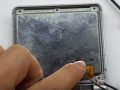
Here are some pictures for anyone interested


Here is a picture of the casing in the circle is where you need to remove the plastic to fit the voltage converter

The orange one is the one I modded, the nintendo classic one is a original 101.
The modded one seems to be a bit brighter than the original, maybe if I adjusted the potentiometer a bit more they could get to the same brightness levels but I prefer it this way.

Here is a picture of the casing in the circle is where you need to remove the plastic to fit the voltage converter
The orange one is the one I modded, the nintendo classic one is a original 101.
The modded one seems to be a bit brighter than the original, maybe if I adjusted the potentiometer a bit more they could get to the same brightness levels but I prefer it this way.
I used the same voltage regulator as you and didn't follow the photos on one of the feedback pages at all.
I identified the solder points on the board as voltage in, ground, and screen output.
Soldered to the positive and negative battery terminals with the included 0.1mm jumper wire
If you havent used jumper wire before its laminated so just touch the tip with soldering iron to expose bare copper to solder.
Soldered the screen output to the positive terminal on the screen ribbon cable using kapton tape to insulate between the two contacts. The negative/ground terminal should be resoldered back in place.
I did the mod the same way on my AGB-001 and measured 11.7v when using rechargables, I havent meaured on the AGS yet but assume its getting the same voltage.
Same voltage regulator? Which one are you talking about. In this thread I see people using the pololu or the ardrino one. I actually ordered both just in case.
Oh ok. Do you happen to have any pictures of your mod?
A little update.
So I ordered a few parts to experiment with. So to me, it's the best to get either the Pololu or the backlit controller from BennVenn. The Pololu is smaller in width and height but a little thicker, whereas the BennVenn is slightly bigger in width and height but thinner/flatter. Everything else is way too big...avoid them if you can.
Now, I've tried the mod with my AGS CPU 01...and didn't get what i wanted.
Here's what I did:
1. I seperated the two contact pads on the back of the screen, wicked the lower pad and used a kapton tape to tape it back on the the pad. I scrapped some tape off the negative side to prepare to solder it back to the upper pad. I tape a upper pad (not covering the terminal), solder the negative terminal back on and then solder a 30awg wire onto the positive terminal. Then I feed the ribbon cable and wire back through to the lower housing.
2. On the lower housing, I feed the wire back to the bottom of the board to finish it off. I followed what everyone did here. On the pololu, I solder the cable to the screen to Vout, Gnd to the contact point next to the chip (had a hard time making the solder stick to it but i double triple check my work to make sure it's not bridging any pin on the chip, and Vin to C1 on the power switch.
So I've turned it on...there's sound but I can't see anything on the screen. However, if I shine a flashlight directly on it I can see something. Reading up on it, it sounds like this is exactly what will happen if I simply connect AGS 101 display onto a AGS001 board...
That it's not getting enough power.
What did I do wrong?
I read some post a couple pages back and some of you seem need to "lift" pin 34 on the display connector. But isn't the point of separating the the contact pad back of the display to disconnect it from the power of connector and get it straight from the Pololu?
crazyfrog1 solder it straight to the battery terminal...so maybe I'll play around with that.
I hope to get this to work...otherwise, I need to get a non CPU 01 board and get rid of this one. The BennVenn chip are meant to go to my friends GBA SP so I might try that setup later on.
Also....man this set up is so pricey...if someone is doing this from scratch (like no GBA SP)...I'll say just buy an AGS 101...it's cheaper. AGS 101 mod really only make sense on the AGB 001 where you can't buy one unless you're getting a pre-modded unit which are a bit pricey.
I've been following the steps detailed at the start of this. My screen is very dark. Have I blown the back light?
Also I haven't put the second wire in, from the screen connector, will this solve my problem?
Any help would be appreciated.
Thanks.
Also I haven't put the second wire in, from the screen connector, will this solve my problem?
Any help would be appreciated.
Thanks.
Ok so it was my fault. I was trying to put in the brightness mod and the connection came off. That’s why the light wasn’t on. Completely forgotten I have done this.
Unfortunately I also blew the pololu...I was testing it. So I have to order another one. Ugh
Now I’ve installed the mod correctly. Everything seems to work. After tweaking the trim pot the display looks great.
I forgot to take picture. But it’s virtually the same as bazahazano expect I didn’t:
-cut traces to pin 34
-solder vout to pin 34
Instead I:
1. Seperate the positive (left side) of the display from upper and lower
2. Solder vout to upper positive on back of display.
I prefer this method over the trace cut cause I figure it easily reversible. And works on any of the gba sp board. Not just cpu 10 and 11.
Tips:
-on display, I wicked the bottom pad to remove some solder. Just trying to keep the back as flat as possible...might not be necessary though
-if your doing the brightness mod:1. Use lots of flux when you’re soldering to pin 33...it’s tough I tape the wire down and held the wire with a needle point tweezer 2. Make sure you have the correct resistor size...my first one is too big and second one is tiny af...I got tired of ordering part and just made the second on work
-soldering to next to the cpu for GND is a pain...alternatively I think you can use positive and negative terminal as vin and gnd.
- Oh one more doing, I wasn't familiar with SMD resistor and order the wrong size. SMD resistor are label with a 4 digit number, e.g. 0402, 0805, 1206, 2512... these number are sizes of the resistor. For example 0402 is 0.04inches x 0.02 inches..and 2512 is 0.25in. x 0.12in...I sure you see where those number came from. I recommend ordering a 0805 but you can use 1206 if you think it's too small for you to work with. DO NOT order a 2512 or 0402...they're too big and too small...lol
Last edited by wtfman,

Hi, sorry to bump but I have questions regarding the step-up regulator to be used. I can't buy from AliExpress nor from BennVenn as shipping would cost me an arm and a leg. However, I did find some step-up regulators from my local online store and one of them looks exactly the same as the one from AliExpress. Has anyone tried doing this mod with any of those regulators? Do they fit properly?
Here are the pics of the ones I saw:


Here are the pics of the ones I saw:


Similar threads
- Replies
- 1
- Views
- 2K
- Replies
- 12
- Views
- 5K
- Replies
- 1
- Views
- 939
Site & Scene News
New Hot Discussed
-
-
58K views
Nintendo Switch firmware 18.0.0 has been released
It's the first Nintendo Switch firmware update of 2024. Made available as of today is system software version 18.0.0, marking a new milestone. According to the patch... -
29K views
GitLab has taken down the Suyu Nintendo Switch emulator
Emulator takedowns continue. Not long after its first release, Suyu emulator has been removed from GitLab via a DMCA takedown. Suyu was a Nintendo Switch emulator... -
21K views
Atmosphere CFW for Switch updated to pre-release version 1.7.0, adds support for firmware 18.0.0
After a couple days of Nintendo releasing their 18.0.0 firmware update, @SciresM releases a brand new update to his Atmosphere NX custom firmware for the Nintendo...by ShadowOne333 94 -
18K views
Wii U and 3DS online services shutting down today, but Pretendo is here to save the day
Today, April 8th, 2024, at 4PM PT, marks the day in which Nintendo permanently ends support for both the 3DS and the Wii U online services, which include co-op play...by ShadowOne333 176 -
15K views
GBAtemp Exclusive Introducing tempBOT AI - your new virtual GBAtemp companion and aide (April Fools)
Hello, GBAtemp members! After a prolonged absence, I am delighted to announce my return and upgraded form to you today... Introducing tempBOT AI 🤖 As the embodiment... -
12K views
Pokemon fangame hosting website "Relic Castle" taken down by The Pokemon Company
Yet another casualty goes down in the never-ending battle of copyright enforcement, and this time, it hit a big website which was the host for many fangames based and...by ShadowOne333 65 -
11K views
MisterFPGA has been updated to include an official release for its Nintendo 64 core
The highly popular and accurate FPGA hardware, MisterFGPA, has received today a brand new update with a long-awaited feature, or rather, a new core for hardcore...by ShadowOne333 51 -
11K views
Apple is being sued for antitrust violations by the Department of Justice of the US
The 2nd biggest technology company in the world, Apple, is being sued by none other than the Department of Justice of the United States, filed for antitrust...by ShadowOne333 80 -
10K views
The first retro emulator hits Apple's App Store, but you should probably avoid it
With Apple having recently updated their guidelines for the App Store, iOS users have been left to speculate on specific wording and whether retro emulators as we... -
9K views
"TMNT: The Hyperstone Heist" for the SEGA Genesis / Mega Drive gets a brand new DX romhack with new features
The romhacking community is always a source for new ways to play retro games, from completely new levels or stages, characters, quality of life improvements, to flat...by ShadowOne333 36
-
-
-
223 replies
Nintendo Switch firmware 18.0.0 has been released
It's the first Nintendo Switch firmware update of 2024. Made available as of today is system software version 18.0.0, marking a new milestone. According to the patch...by Chary -
176 replies
Wii U and 3DS online services shutting down today, but Pretendo is here to save the day
Today, April 8th, 2024, at 4PM PT, marks the day in which Nintendo permanently ends support for both the 3DS and the Wii U online services, which include co-op play...by ShadowOne333 -
169 replies
GBAtemp Exclusive Introducing tempBOT AI - your new virtual GBAtemp companion and aide (April Fools)
Hello, GBAtemp members! After a prolonged absence, I am delighted to announce my return and upgraded form to you today... Introducing tempBOT AI 🤖 As the embodiment...by tempBOT -
146 replies
GitLab has taken down the Suyu Nintendo Switch emulator
Emulator takedowns continue. Not long after its first release, Suyu emulator has been removed from GitLab via a DMCA takedown. Suyu was a Nintendo Switch emulator...by Chary -
96 replies
The first retro emulator hits Apple's App Store, but you should probably avoid it
With Apple having recently updated their guidelines for the App Store, iOS users have been left to speculate on specific wording and whether retro emulators as we...by Scarlet -
94 replies
Atmosphere CFW for Switch updated to pre-release version 1.7.0, adds support for firmware 18.0.0
After a couple days of Nintendo releasing their 18.0.0 firmware update, @SciresM releases a brand new update to his Atmosphere NX custom firmware for the Nintendo...by ShadowOne333 -
80 replies
Apple is being sued for antitrust violations by the Department of Justice of the US
The 2nd biggest technology company in the world, Apple, is being sued by none other than the Department of Justice of the United States, filed for antitrust...by ShadowOne333 -
74 replies
Delta emulator now available on the App Store for iOS
The time has finally come, and after many, many years (if not decades) of Apple users having to side load emulator apps into their iOS devices through unofficial...by ShadowOne333 -
65 replies
Pokemon fangame hosting website "Relic Castle" taken down by The Pokemon Company
Yet another casualty goes down in the never-ending battle of copyright enforcement, and this time, it hit a big website which was the host for many fangames based and...by ShadowOne333 -
53 replies
Nintendo "Indie World" stream announced for April 17th, 2024
Nintendo has recently announced through their social media accounts that a new Indie World stream will be airing tomorrow, scheduled for April 17th, 2024 at 7 a.m. PT...by ShadowOne333
-
Popular threads in this forum
General chit-chat
-
 Psionic Roshambo
Loading…
Psionic Roshambo
Loading…
-
-
-
-
-
-
-
-
-
-
-
-
-
-
-
-
-
-
-
-
-
 @
RedColoredStars:
There is an actual trailer with footage too. lol. Going to watch it tonight. Grabbed it from... a place.
@
RedColoredStars:
There is an actual trailer with footage too. lol. Going to watch it tonight. Grabbed it from... a place. -
-
 @
SylverReZ:
@Psionic Roshambo, JonTron's back yet again until he disappears into the void for another 6 or so months.+1
@
SylverReZ:
@Psionic Roshambo, JonTron's back yet again until he disappears into the void for another 6 or so months.+1 -
-