

You are using an out of date browser. It may not display this or other websites correctly.
You should upgrade or use an alternative browser.
You should upgrade or use an alternative browser.


- Joined
- Sep 2, 2020
- Messages
- 1,270
- Trophies
- 0
- Age
- 39
- Location
- TORONTO
- Website
- form.jotform.com
- XP
- 2,201
- Country

1.1nF from measure, my guess is 1200pf 0201 caps, maybe 20-25v range since its on backlight circuitlease name the component Nintendo switch litle ?? what size and value ??:
View attachment 307446

Hello,
Can someone tell me which components are involved here? They are labeled with: 1B W79.
Have completely different values to a donor board. The charging current of the switch is 0A!
M39 has already been changed twice. He's not the problem. There is also no 3.3V at the cap above the P13 USB. Does somebody has any idea?
*edit*
I think the chip on the two has a defect. The chip is marked "A6 EN". Does anyone know of a source for this part?
Last edited by ReGa,

Mosfet https://www.aliexpress.com/item/1005002504110411.html?spm=a2g0o.cart.0.0.9c6b3c008tsnMg&mp=1Hello,
Can someone tell me which components are involved here? They are labeled with: 1B W79.
Have completely different values to a donor board. The charging current of the switch is 0A!
M39 has already been changed twice. He's not the problem. There is also no 3.3V at the cap above the P13 USB. Does somebody has any idea?
*edit*
I think the chip on the two has a defect. The chip is marked "A6 EN". Does anyone know of a source for this part?
View attachment 309709

Yes, ceramic capacitor size 0201 voltage 10v more then enough, messure the resistors, if they are 50 ohm go with 100pf, "7.3.4 Filtering Remote junction temperature sensors are usually implemented in a noisy environment. Noise is most often created by fast digital signals, and it can corrupt measurements. The TMP451 device has a built-in, 65-kHz filter on the inputs of D+ and D– to minimize the effects of noise. However, a bypass capacitor placed differentially across the inputs of the remote temperature sensor is recommended to make the application more robust against unwanted coupled signals. For this capacitor, select a value of between 100 pF and 1 nF. Some applications attain better overall accuracy with additional series resistance; however, this increased accuracy is applicationspecific. When series resistance is added, the total value should not be greater than 1 kΩ. If filtering is required, suggested component values are 100 pF and 50 Ω on each input; exact values are application-specific. "
in my attempt to replace the USBc port, I blew this chip off the board and may have damaged it. Can anyone identify what it is? Also does it go on the board in a specific way? I was able to reattach but dont want to fry the board if I power it on and its not on the right way
- Joined
- Sep 2, 2020
- Messages
- 1,270
- Trophies
- 0
- Age
- 39
- Location
- TORONTO
- Website
- form.jotform.com
- XP
- 2,201
- Country
in my attempt to replace the USBc port, I blew this chip off the board and may have damaged it. Can anyone identify what it is? Also does it go on the board in a specific way? I was able to reattach but dont want to fry the board if I power it on and its not on the right way
TPD2E1B06DRLR
Attachments
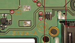

Need help! I am replacing the M92T36 chip and messed up the two 100k 50uw caps above the chip. I got replacements and am going to replace them. On top of the two 100k capacitors the trace got scratched and now they are connected... does this matter? It looks like they do connect based on the trace on the board.. the bottom of the chips do not touch. I uploaded a picture. The red box are the two contact points that touch, the yellow box points do not touch.
Any advice/insight would be appreciated. Thanks in advance
Any advice/insight would be appreciated. Thanks in advance
- Joined
- Sep 2, 2020
- Messages
- 1,270
- Trophies
- 0
- Age
- 39
- Location
- TORONTO
- Website
- form.jotform.com
- XP
- 2,201
- Country
Need help! I am replacing the M92T36 chip and messed up the two 100k 50uw caps above the chip. I got replacements and am going to replace them. On top of the two 100k capacitors the trace got scratched and now they are connected... does this matter? It looks like they do connect based on the trace on the board.. the bottom of the chips do not touch. I uploaded a picture. The red box are the two contact points that touch, the yellow box points do not touch.
Any advice/insight would be appreciated. Thanks in advance
they are supposed connected, does not matter
Thanks for helping me out. you OGthey are supposed connected, does not matter
Replaced the M92T36 chip and now my switch works!! it wasn't docking or charging. Now it is. However, now I cant get into RCM mode. The switch does go into the mode but will not accept payload. I can exit by holding down the power button. Before replacing the M92T36 chip, I had no problem getting into RCM/sending payload. any ideas?

Looking for help please to identify this circled resistor in the area near point D on the oled switch, and also function/importance if anyone knows. Have unfortunately killed it installing the Hwfly 4.1
Need help finding a replacement chip for this. Ordered from both EBAY AND Kasyn and it wasn't the right part... both times was sent the emi coil that goes on the back of the board where the p13 chip is... and bigger (See pic below)
Does anyone know where I can find the actual chip??

THIS IS WHAT I WAS SENT:

@jkyoho any thoughts?
Does anyone know where I can find the actual chip??
THIS IS WHAT I WAS SENT:
@jkyoho any thoughts?
Last edited by CoolRunninJA,
Similar threads
- Replies
- 1
- Views
- 451
- Replies
- 0
- Views
- 236
- Replies
- 2
- Views
- 1K
- Replies
- 10
- Views
- 5K
- Replies
- 24
- Views
- 9K
Site & Scene News
New Hot Discussed
-
-
63K views
Nintendo Switch firmware 18.0.0 has been released
It's the first Nintendo Switch firmware update of 2024. Made available as of today is system software version 18.0.0, marking a new milestone. According to the patch... -
25K views
Atmosphere CFW for Switch updated to pre-release version 1.7.0, adds support for firmware 18.0.0
After a couple days of Nintendo releasing their 18.0.0 firmware update, @SciresM releases a brand new update to his Atmosphere NX custom firmware for the Nintendo...by ShadowOne333 107 -
20K views
Wii U and 3DS online services shutting down today, but Pretendo is here to save the day
Today, April 8th, 2024, at 4PM PT, marks the day in which Nintendo permanently ends support for both the 3DS and the Wii U online services, which include co-op play...by ShadowOne333 179 -
16K views
GBAtemp Exclusive Introducing tempBOT AI - your new virtual GBAtemp companion and aide (April Fools)
Hello, GBAtemp members! After a prolonged absence, I am delighted to announce my return and upgraded form to you today... Introducing tempBOT AI 🤖 As the embodiment... -
13K views
The first retro emulator hits Apple's App Store, but you should probably avoid it
With Apple having recently updated their guidelines for the App Store, iOS users have been left to speculate on specific wording and whether retro emulators as we... -
13K views
Pokemon fangame hosting website "Relic Castle" taken down by The Pokemon Company
Yet another casualty goes down in the never-ending battle of copyright enforcement, and this time, it hit a big website which was the host for many fangames based and...by ShadowOne333 66 -
13K views
MisterFPGA has been updated to include an official release for its Nintendo 64 core
The highly popular and accurate FPGA hardware, MisterFGPA, has received today a brand new update with a long-awaited feature, or rather, a new core for hardcore...by ShadowOne333 54 -
12K views
Delta emulator now available on the App Store for iOS
The time has finally come, and after many, many years (if not decades) of Apple users having to side load emulator apps into their iOS devices through unofficial...by ShadowOne333 96 -
10K views
"TMNT: The Hyperstone Heist" for the SEGA Genesis / Mega Drive gets a brand new DX romhack with new features
The romhacking community is always a source for new ways to play retro games, from completely new levels or stages, characters, quality of life improvements, to flat...by ShadowOne333 36 -
10K views
Anbernic announces RG35XX 2024 Edition retro handheld
Retro handheld manufacturer Anbernic is releasing a refreshed model of its RG35XX handheld line. This new model, named RG35XX 2024 Edition, features the same...
-
-
-
225 replies
Nintendo Switch firmware 18.0.0 has been released
It's the first Nintendo Switch firmware update of 2024. Made available as of today is system software version 18.0.0, marking a new milestone. According to the patch...by Chary -
179 replies
Wii U and 3DS online services shutting down today, but Pretendo is here to save the day
Today, April 8th, 2024, at 4PM PT, marks the day in which Nintendo permanently ends support for both the 3DS and the Wii U online services, which include co-op play...by ShadowOne333 -
169 replies
GBAtemp Exclusive Introducing tempBOT AI - your new virtual GBAtemp companion and aide (April Fools)
Hello, GBAtemp members! After a prolonged absence, I am delighted to announce my return and upgraded form to you today... Introducing tempBOT AI 🤖 As the embodiment...by tempBOT -
107 replies
Atmosphere CFW for Switch updated to pre-release version 1.7.0, adds support for firmware 18.0.0
After a couple days of Nintendo releasing their 18.0.0 firmware update, @SciresM releases a brand new update to his Atmosphere NX custom firmware for the Nintendo...by ShadowOne333 -
97 replies
The first retro emulator hits Apple's App Store, but you should probably avoid it
With Apple having recently updated their guidelines for the App Store, iOS users have been left to speculate on specific wording and whether retro emulators as we...by Scarlet -
96 replies
Delta emulator now available on the App Store for iOS
The time has finally come, and after many, many years (if not decades) of Apple users having to side load emulator apps into their iOS devices through unofficial...by ShadowOne333 -
72 replies
Nintendo Switch firmware update 18.0.1 has been released
A new Nintendo Switch firmware update is here. System software version 18.0.1 has been released. This update offers the typical stability features as all other...by Chary -
66 replies
Pokemon fangame hosting website "Relic Castle" taken down by The Pokemon Company
Yet another casualty goes down in the never-ending battle of copyright enforcement, and this time, it hit a big website which was the host for many fangames based and...by ShadowOne333 -
54 replies
MisterFPGA has been updated to include an official release for its Nintendo 64 core
The highly popular and accurate FPGA hardware, MisterFGPA, has received today a brand new update with a long-awaited feature, or rather, a new core for hardcore...by ShadowOne333 -
53 replies
Nintendo "Indie World" stream announced for April 17th, 2024
Nintendo has recently announced through their social media accounts that a new Indie World stream will be airing tomorrow, scheduled for April 17th, 2024 at 7 a.m. PT...by ShadowOne333
-
Popular threads in this forum
General chit-chat
-
 Psionic Roshambo
Loading…
Psionic Roshambo
Loading… -
 Veho
Loading…
Veho
Loading…
-
-
-
-
-
-
-
-
-
-
-
-
-
-
-
-
-
-
@
Veho:
Illinois is working to ban toxic food additives that have been banned for decades in other countries; additives that can be replaced and all those countries still have Skittles and Mountain Dew. Title of the piece: GUBMINT WANTS TO TAKE AWAY YOUR CANDY
-
-
 @
SylverReZ:
@Veho, Sounds and smells like bullshit. They don't give you cancer, and California should know that. I don't get why they stick labels that say "may or may not cause reproductive harm or cancer".
@
SylverReZ:
@Veho, Sounds and smells like bullshit. They don't give you cancer, and California should know that. I don't get why they stick labels that say "may or may not cause reproductive harm or cancer". -
-
-
-
-