


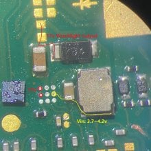
Hello everyone. I ran into a problem with the backlight on the Switch Lite-no 17 volts. The components are all in order - I moved them from working to non-working and vice versa. Now I am interested in a specific question - where is the 17 V that should go from the inductor. I measured on the working one, they are only already on the capacitor that is next to the diode. In the photo, I marked everything. I read all the topics on problems with the backlight , I did not find an answer to my question

You are using an out of date browser. It may not display this or other websites correctly.
You should upgrade or use an alternative browser.
You should upgrade or use an alternative browser.
- Joined
- Sep 2, 2020
- Messages
- 1,270
- Trophies
- 0
- Age
- 39
- Location
- TORONTO
- Website
- form.jotform.com
- XP
- 2,201
- Country

https://www.ti.com/lit/ds/symlink/tps61163a.pdf?ts=1620688796425
check the backlight ic datasheet.
the inductor has 3.7~4.2v vin at bottom pin. Top pin is SW pin
17v goes to the cap next to the diode as well as the test pad from the top(red lines)
check the backlight ic datasheet.
the inductor has 3.7~4.2v vin at bottom pin. Top pin is SW pin
17v goes to the cap next to the diode as well as the test pad from the top(red lines)
Attachments

I would buzz through the 17v drive line through to the backlight FPC on the daughterboard. The connector linking the two boards is famous for burning out or losing connectivity at one end. Normally you get button faults at the same time which are a good indicator.
If the line is broken in any way, then the backlight IC will only output a few volts no the full 17v you expect. As jkyoho said the datasheet should have a lot of good information to help you on your journey.
If you have a known working unit you might want to try different combinations of boards to zero down to faults with the connectors linking the boards or the ribbon linking them etc.
Sheriff.

I second what he said, My lite had the backlight trace blown on the ribbon cable, What I did until I got a replacement was run a magnet wire from the main board to the left board to get the backlight working.

Hi. This is my first message in this group. Nice to see so many helpful comments.
I have a water damaged Switch Lite which I am having issues to get the back light working.
The digitizer and screen are working as per normal.
I have taken voltages from this damaged board and compared to a working board, while attached to a known working backlight, connecting ribbon cable and side board.
I noticed that the damaged board does not go up to 17V as it should. I have also swapped the BGA 9ball BL chip.
My noob question: Is the backlight dependent on any other component other than the BGA chip and this cluster?
Last edited by DinSg,
- Joined
- Sep 2, 2020
- Messages
- 1,270
- Trophies
- 0
- Age
- 39
- Location
- TORONTO
- Website
- form.jotform.com
- XP
- 2,201
- Country
The daughter board works fine when tested with a good board.
i have also taken the BGA chip from another board, which I know the backlight is working.
Made sure all the balls are good and transferred to this damaged board and still nothing. No 17v.
The output voltages where is it supposed to be at 17v are at Vin...
I also have transferred the BGA chip from board to board and all the backlights work, except for this board! Arghhhhh
Last edited by DinSg,
I was replacing the joycon thumbsticks on nintendo switch lite. Everything was perfect. When I'm done I was trying to power the device on and Didn't power on. Then plug into charger it powered on. Opened it up and checked again everything was perfect. Closed everything back and backlight wasn't working. Brought home and checked under the microscope I was only seeing 4.3v instead of 17v. When I fold that flex ribbon between motherboard and sub board, Backlight came back. I ordered that flex and waiting for shipping. I found this forum when I was searching. This is the only source that I can find. Thanks guys it was helpful thread for diagnosing my problem. I'll give you guys update when I get that flex. It's really crazy that flex break that easy. Man I was about to give up and buy a customer new switch lite... I mostly do motherboard repair I wasn't gonna get that joycon replacement I knew something was gonna happen....
- Joined
- Oct 19, 2009
- Messages
- 313
- Trophies
- 1
- Age
- 38
- Location
- manchester
- Website
- Visit site
- XP
- 643
- Country

I was replacing the joycon thumbsticks on nintendo switch lite. Everything was perfect. When I'm done I was trying to power the device on and Didn't power on. Then plug into charger it powered on. Opened it up and checked again everything was perfect. Closed everything back and backlight wasn't working. Brought home and checked under the microscope I was only seeing 4.3v instead of 17v. When I fold that flex ribbon between motherboard and sub board, Backlight came back. I ordered that flex and waiting for shipping. I found this forum when I was searching. This is the only source that I can find. Thanks guys it was helpful thread for diagnosing my problem. I'll give you guys update when I get that flex. It's really crazy that flex break that easy. Man I was about to give up and buy a customer new switch lite... I mostly do motherboard repair I wasn't gonna get that joycon replacement I knew something was gonna happen....
I had a similar problem, but I replaced the connector twice, I was convinced it was perfect, but it was because I changed it again and the backlight came back on.

Assuming the backlight IC has an enabler pin, so that this chip wakes up and switches the inductor in order to boost voltage to ~17V, what enables it? Is it the APU? If it is, would you happen to know which pin is it and how many volts does it get to enable?check backlight pins diode measure with both side daughter board extension cable connect.(NO battery or charger of course)
Often time if no connection to backlight socket, 17v will not generate
- Joined
- Sep 2, 2020
- Messages
- 1,270
- Trophies
- 0
- Age
- 39
- Location
- TORONTO
- Website
- form.jotform.com
- XP
- 2,201
- Country
My son had his switch damaged by another kid. Backlight issue as well. My question is as I troubleshoot the issue with my son's is there a way I can power on the backlight externally to do a data transfer to a new unit as I trouble shoot this one any suggestions.

Can I ask u how did u measured? During the battery is connected??check the backlight ic datasheet.
the inductor has 3.7~4.2v vin at bottom pin. Top pin is SW pin
17v goes to the cap next to the diode as well as the test pad from the top(red lines)
I have 0 voltage at the Pont who should have 17v. I think therefore the ic should be damaged?
The screen itselfs works fine just the backlight didn’t work for me
- Joined
- Sep 2, 2020
- Messages
- 1,270
- Trophies
- 0
- Age
- 39
- Location
- TORONTO
- Website
- form.jotform.com
- XP
- 2,201
- Country
Sure you need to have battery in and turn it on when measuring the backlight voltage.Can I ask u how did u measured? During the battery is connected??
I have 0 voltage at the Pont who should have 17v. I think therefore the ic should be damaged?
The screen itselfs works fine just the backlight didn’t work for me
But since you don't have backlight, you should rather check diode reading(like here) on the backlight connector or continuity between long cable from mainboard to joycon/daughter board.
Thanks for your fast reply! First of all i would let you know that i am not a professional in this field and bought the defect switch as a kind of hobbySure you need to have battery in and turn it on when measuring the backlight voltage.
But since you don't have backlight, you should rather check diode reading on the backlight connector or continuity between long cable from mainboard to joycon/daughter board.

I measured the voltage with one pin on metal as gnd and the other one in the field (above them) and its smoked a bit
but the switch is working as well... just the backlight has the fault.Regarding the measurement on the daughter board i think it is necessary to have an microsokop or?
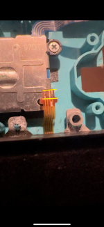
The attached pictures shows the cleaned backlight cable.. all of the conductor path works
Attachments
- Joined
- Sep 2, 2020
- Messages
- 1,270
- Trophies
- 0
- Age
- 39
- Location
- TORONTO
- Website
- form.jotform.com
- XP
- 2,201
- Country
clearly water damage and this backlight cable is badThanks for your fast reply! First of all i would let you know that i am not a professional in this field and bought the defect switch as a kind of hobby
I measured the voltage with one pin on metal as gnd and the other one in the field (above them) and its smoked a bit
Regarding the measurement on the daughter board i think it is necessary to have an microsokop or?
The attached pictures shows the cleaned backlight cable.. all of the conductor path works
Post automatically merged:
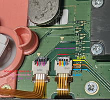
If you have a giant round prob lead, avoiding short-out the pins next to each other around any connector, i.e backlight connector. You may end up leading high voltage(17v) short through the pwm or signal pin burn out the backlight driver chip(since you mentioned smoke).
You could measure the backlight reading from the trace I marked on each color.
Last edited by jkyoho,
Thanks for ur reply! That means the backlight cable is totally damaged and can’t be use anymore?clearly water damage and this backlight cable is bad
Post automatically merged:
If you have a giant round prob lead, avoiding short-out the pins next to each other around any connector, i.e backlight connector. You may end up leading high voltage(17v) short through the pwm or signal pin burn out the backlight driver chip(since you mentioned smoke).
You could measure the backlight reading from the trace I marked on each color.
Let me check the traces later
- Joined
- Sep 2, 2020
- Messages
- 1,270
- Trophies
- 0
- Age
- 39
- Location
- TORONTO
- Website
- form.jotform.com
- XP
- 2,201
- Country
That's correct, unless you are capable to repair the broken traces on the cable.Thanks for ur reply! That means the backlight cable is totally damaged and can’t be use anymore?
Let me check the traces later
I would just replace the entire LCD,because from experience you might end up having water mark left between LCD& backlight panel after you manage to repair the cable and everything.
Okay. Is there any way to check the other circuit before ordering a new lcd? To avoid any mistakes?That's correct, unless you are capable to repair the broken traces on the cable.
I would just replace the entire LCD,because from experience you might end up having water mark left between LCD& backlight panel after you manage to repair the cable and everything.
- Joined
- Sep 2, 2020
- Messages
- 1,270
- Trophies
- 0
- Age
- 39
- Location
- TORONTO
- Website
- form.jotform.com
- XP
- 2,201
- Country
I assume you only having backlight issue.Okay. Is there any way to check the other circuit before ordering a new lcd? To avoid any mistakes?
check the backlight connector diode reading when battery and backlight cable disconnected.
Similar threads
- Replies
- 0
- Views
- 277
- Replies
- 2
- Views
- 453
- Replies
- 4
- Views
- 1K
- Replies
- 2
- Views
- 706
- Replies
- 0
- Views
- 924
Site & Scene News
New Hot Discussed
-
-
63K views
Nintendo Switch firmware 18.0.0 has been released
It's the first Nintendo Switch firmware update of 2024. Made available as of today is system software version 18.0.0, marking a new milestone. According to the patch... -
25K views
Atmosphere CFW for Switch updated to pre-release version 1.7.0, adds support for firmware 18.0.0
After a couple days of Nintendo releasing their 18.0.0 firmware update, @SciresM releases a brand new update to his Atmosphere NX custom firmware for the Nintendo...by ShadowOne333 107 -
21K views
Wii U and 3DS online services shutting down today, but Pretendo is here to save the day
Today, April 8th, 2024, at 4PM PT, marks the day in which Nintendo permanently ends support for both the 3DS and the Wii U online services, which include co-op play...by ShadowOne333 179 -
16K views
GBAtemp Exclusive Introducing tempBOT AI - your new virtual GBAtemp companion and aide (April Fools)
Hello, GBAtemp members! After a prolonged absence, I am delighted to announce my return and upgraded form to you today... Introducing tempBOT AI 🤖 As the embodiment... -
13K views
The first retro emulator hits Apple's App Store, but you should probably avoid it
With Apple having recently updated their guidelines for the App Store, iOS users have been left to speculate on specific wording and whether retro emulators as we... -
13K views
Pokemon fangame hosting website "Relic Castle" taken down by The Pokemon Company
Yet another casualty goes down in the never-ending battle of copyright enforcement, and this time, it hit a big website which was the host for many fangames based and...by ShadowOne333 66 -
13K views
MisterFPGA has been updated to include an official release for its Nintendo 64 core
The highly popular and accurate FPGA hardware, MisterFGPA, has received today a brand new update with a long-awaited feature, or rather, a new core for hardcore...by ShadowOne333 54 -
12K views
Delta emulator now available on the App Store for iOS
The time has finally come, and after many, many years (if not decades) of Apple users having to side load emulator apps into their iOS devices through unofficial...by ShadowOne333 96 -
10K views
"TMNT: The Hyperstone Heist" for the SEGA Genesis / Mega Drive gets a brand new DX romhack with new features
The romhacking community is always a source for new ways to play retro games, from completely new levels or stages, characters, quality of life improvements, to flat...by ShadowOne333 36 -
10K views
Anbernic announces RG35XX 2024 Edition retro handheld
Retro handheld manufacturer Anbernic is releasing a refreshed model of its RG35XX handheld line. This new model, named RG35XX 2024 Edition, features the same...
-
-
-
225 replies
Nintendo Switch firmware 18.0.0 has been released
It's the first Nintendo Switch firmware update of 2024. Made available as of today is system software version 18.0.0, marking a new milestone. According to the patch...by Chary -
179 replies
Wii U and 3DS online services shutting down today, but Pretendo is here to save the day
Today, April 8th, 2024, at 4PM PT, marks the day in which Nintendo permanently ends support for both the 3DS and the Wii U online services, which include co-op play...by ShadowOne333 -
169 replies
GBAtemp Exclusive Introducing tempBOT AI - your new virtual GBAtemp companion and aide (April Fools)
Hello, GBAtemp members! After a prolonged absence, I am delighted to announce my return and upgraded form to you today... Introducing tempBOT AI 🤖 As the embodiment...by tempBOT -
107 replies
Atmosphere CFW for Switch updated to pre-release version 1.7.0, adds support for firmware 18.0.0
After a couple days of Nintendo releasing their 18.0.0 firmware update, @SciresM releases a brand new update to his Atmosphere NX custom firmware for the Nintendo...by ShadowOne333 -
97 replies
The first retro emulator hits Apple's App Store, but you should probably avoid it
With Apple having recently updated their guidelines for the App Store, iOS users have been left to speculate on specific wording and whether retro emulators as we...by Scarlet -
96 replies
Delta emulator now available on the App Store for iOS
The time has finally come, and after many, many years (if not decades) of Apple users having to side load emulator apps into their iOS devices through unofficial...by ShadowOne333 -
73 replies
Nintendo Switch firmware update 18.0.1 has been released
A new Nintendo Switch firmware update is here. System software version 18.0.1 has been released. This update offers the typical stability features as all other...by Chary -
66 replies
Pokemon fangame hosting website "Relic Castle" taken down by The Pokemon Company
Yet another casualty goes down in the never-ending battle of copyright enforcement, and this time, it hit a big website which was the host for many fangames based and...by ShadowOne333 -
54 replies
MisterFPGA has been updated to include an official release for its Nintendo 64 core
The highly popular and accurate FPGA hardware, MisterFGPA, has received today a brand new update with a long-awaited feature, or rather, a new core for hardcore...by ShadowOne333 -
53 replies
Nintendo "Indie World" stream announced for April 17th, 2024
Nintendo has recently announced through their social media accounts that a new Indie World stream will be airing tomorrow, scheduled for April 17th, 2024 at 7 a.m. PT...by ShadowOne333
-
Popular threads in this forum
General chit-chat

