Hardware Nintendo Switch - SD CARD Alternative Points

Everlasting1337

Well-Known Member
OP
Newcomer
Joined
Dec 26, 2020
Messages
65
Trophies
0
Age
117
XP
176
Country
United States
Hello,
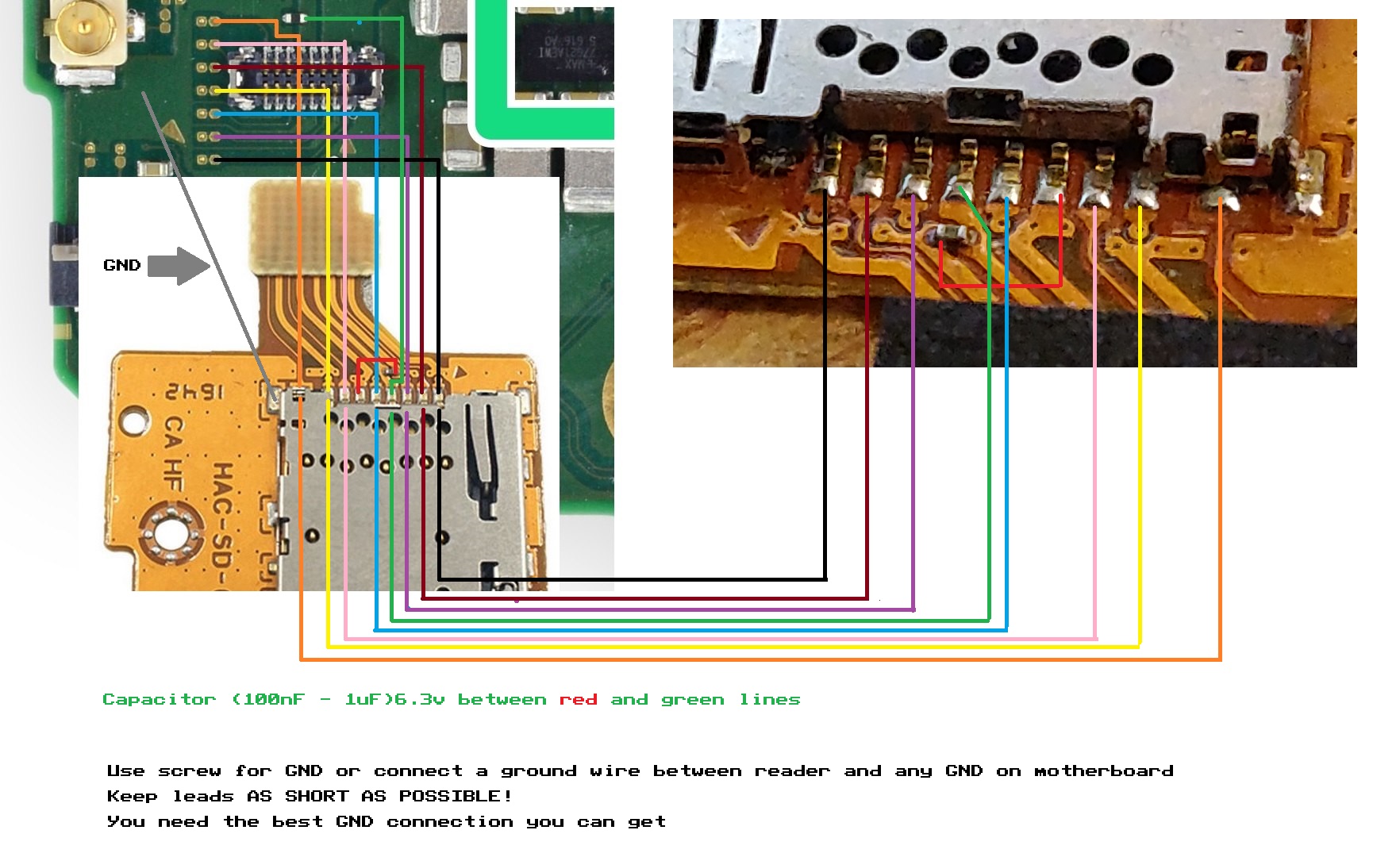
I was doing some testing on the Switch to find the alternative points to match the back. @mattytrog did the pin out for the front some time ago, but we never had a pin out for the back. I have found the black, blue, pink and orange pins. @pyorin Was able to correctly identify where the purple, yellow and brown/burgundy pin goes and has checked all of them too. Due to this, we now have the correct pin out.

Also @MatinatorX has identified the actual part (Molex - Motherboard) to be 5042081610. It is always best to try and replace the actual part, however, if that isn't an option then you have this. I've combined, most of the threads with confirmed working points together as they are quite a few on the site.

This thread now has the complete pinout for the front and back pins.

@pyorin Has confirmed the points and has checked them and has added the correct allocation of the purple, yellow and brown/burgundy pins.
rBdyFLt.png

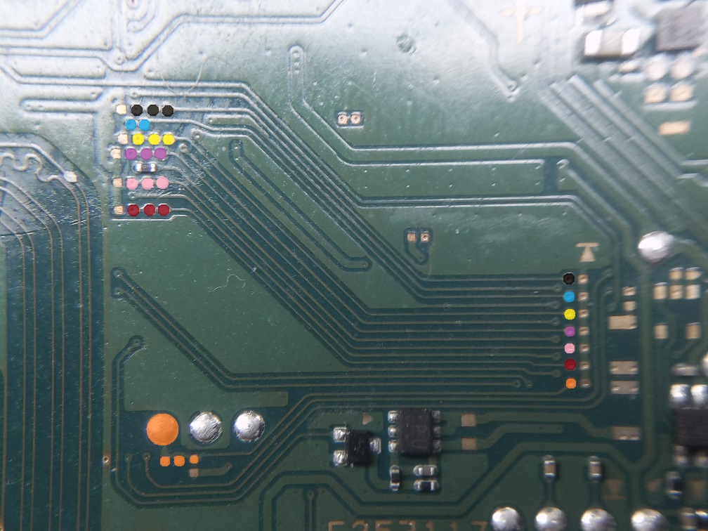
This is @pyorin complete pinout of the back, it shows additionally where the back points lead to. So you now have even more options of deciding where to solder to.
SasxT2hR.jpg

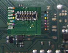
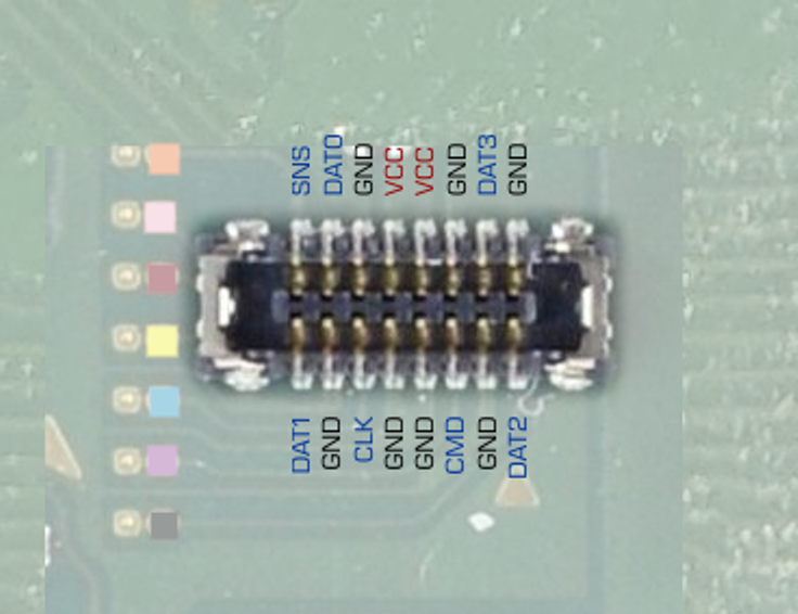
@MatinatorX Also added the pinout for the molex to all the corresponding pins to the SD card below:
sd-png.240129

Also, found @MatinatorX repair video. I've taken the image from the video and added @MatinatorX pinout to the board without the molex connector. This way you can tell where every single pins go and have a clear idea:
9z8NLwE.png

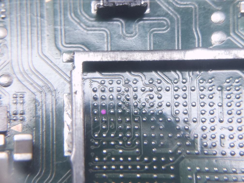
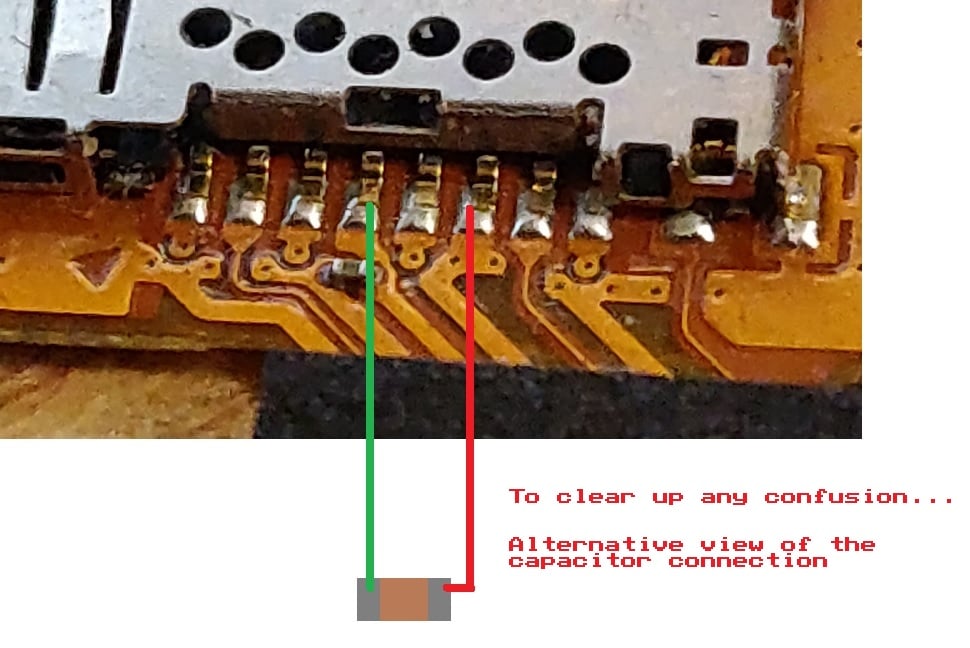
Close up of @MatinatorX repair showing no pinout, shows you where every single trace goes:
OCOZUdY.png

Also this diagram below is from @mattytrog so if you still have the points on the front you can use it them. If you did manage to tear the front test points, the link to the back and you can follow my diagram above:
sd_connection-jpg.191749


sdcap-jpg.191778

Credits:

@mattytrog - Supplying the original pin out for front points that has helped many
@MatinatorX - Supplying pinout of the molex connector and replacement part
@pyorin - Finding the missing point and correcting the diagram
 
Last edited by Everlasting1337,

mitcha

مجاهد صنديد مقاتل عنيد
Member
Joined
Dec 20, 2015
Messages
405
Trophies
0
Location
collo (chullu)
XP
1,761
Country
Algeria
thank you for completing the flip side of the test point ;) , certainly it will help.
as for the purple one , does he not go to the last one not colored (the 3th one counting from UP ) ,in your image ?
 
  • Like
Reactions: Everlasting1337

fvig2001

Well-Known Member
Member
Joined
Aug 21, 2006
Messages
931
Trophies
1
XP
2,926
Country
Philippines
I really wish Nintendo designed this part better since one of my switches has a broken pin (happened when I upgraded my eMMC). Hopefully I can find a shop that can thread an enamel wire for dat2. Btw, I read a thread on reddit about the whole connector that got ripped off complete. How often does that happen?

How important is the ground point on the lower right, the one beside Dat2? I also don't have that pin connected.
 
Last edited by fvig2001,
  • Like
Reactions: Everlasting1337

mitcha

مجاهد صنديد مقاتل عنيد
Member
Joined
Dec 20, 2015
Messages
405
Trophies
0
Location
collo (chullu)
XP
1,761
Country
Algeria
@fvig2001 this issue happen , when you touch frequenly the sd card , when you drop the switch ...
does pins are fragile , they are so tiny.
the best thing is to replace the connector, but you need material ( hot gun ) and good soldering experience.
there are ppl here with no experience who do it at their risk , as far as i know the majority succes

the ground can be connected to the screw of the sd card reader, when it's connected to the main board.
 

Everlasting1337

Well-Known Member
OP
Newcomer
Joined
Dec 26, 2020
Messages
65
Trophies
0
Age
117
XP
176
Country
United States
thank you for completing the flip side of the test point ;) , certainly it will help.
as for the purple one , does he not go to the last one not colored (the 3th one counting from UP ) ,in your image ?

I'm not sure where the purple goes, it didn't go to that missing point on the back. Neither do I know where that one goes either.

I really wish Nintendo designed this part better since one of my switches has a broken pin (happened when I upgraded my eMMC). Hopefully I can find a shop that can thread an enamel wire for dat2. Btw, I read a thread on reddit about the whole connector that got ripped off complete. How often does that happen?

How important is the ground point on the lower right, the one beside Dat2? I also don't have that pin connected.

The Switch Lite has a soldered on SD Module. Which makes it far more sturdier, could this have potentially been the reason why they did it. not sure. But I typically find it's much easier to replace the actual module than a molex connector. You can get the molex connector on Ali Express, but as mentioned by mitcha you need experience as it can melt easily and needs to be aligned correctly.
 

MatinatorX

Hardware Developer
Developer
Joined
Jul 17, 2018
Messages
366
Trophies
1
Website
www.dragoninjector.com
XP
2,538
Country
Canada
FYI a lot of pins on the connector are ground, so if one of them goes missing it does not necessarily mean you are stuck as long as it was a ground pin that went missing. Then again, you probably aren't reading up on missing pins unless you can no longer read MicroSD cards. :P

Can confirm that pinout @mattytrog did is correct, however the red "jumper" is a bit confusing - this is just showing that the ground plane underneath links these two points for the bypass cap. It is not a "wire" you would ever need to solder like the other ones are.

If anyone needs a pinout of the actual MOLEX connector, let me know. A proper connector replacement is not too hard with the right tools - right now we know of one shop in Australia that will do it and two people in Canada that can do it including myself. If anyone knows of repair shops anywhere else that can do this, please let me know so we can point people in the right direction!
 

Everlasting1337

Well-Known Member
OP
Newcomer
Joined
Dec 26, 2020
Messages
65
Trophies
0
Age
117
XP
176
Country
United States
FYI a lot of pins on the connector are ground, so if one of them goes missing it does not necessarily mean you are stuck as long as it was a ground pin that went missing. Then again, you probably aren't reading up on missing pins unless you can no longer read MicroSD cards. :P

Can confirm that pinout @mattytrog did is correct, however the red "jumper" is a bit confusing - this is just showing that the ground plane underneath links these two points for the bypass cap. It is not a "wire" you would ever need to solder like the other ones are.

If anyone needs a pinout of the actual MOLEX connector, let me know. A proper connector replacement is not too hard with the right tools - right now we know of one shop in Australia that will do it and two people in Canada that can do it including myself. If anyone knows of repair shops anywhere else that can do this, please let me know so we can point people in the right direction!

Yeah quite a few are ground, noticed that when was probing around. I guess a pinout of the molex would be nice for the thread, just in case anyone stumbles across it. As for the purple pin, I believe this is the CMD pin for the Micro SD card. Would you happen to know if it leads anywhere else on the motherboard. Thanks
 

Everlasting1337

Well-Known Member
OP
Newcomer
Joined
Dec 26, 2020
Messages
65
Trophies
0
Age
117
XP
176
Country
United States
You're correct, purple is CMD. I haven't probed elsewhere on the motherboard but I'm fairly certain all the SD lines go straight to the SoC. You could check the Switchbrew wiki to see if any of the known pad clusters have it but I don't think so.

Here's the pinout:

View attachment 240129

Awesome, thanks for taking the time to add the pinout to the diagram. I will investigate more. I've added and credited you again on the thread. Thanks for this, I'm sure this will help many people when the time comes.
 

Everlasting1337

Well-Known Member
OP
Newcomer
Joined
Dec 26, 2020
Messages
65
Trophies
0
Age
117
XP
176
Country
United States
I still can't find the purple point, maybe it does just go to the SoC. If anyone does ever find it, do let me know so I can credit you and add the information to the thread.
 

Everlasting1337

Well-Known Member
OP
Newcomer
Joined
Dec 26, 2020
Messages
65
Trophies
0
Age
117
XP
176
Country
United States
@pyorin Welcome back. Long time I haven't seen you around. I've been telling people of your awesome work. Thanks so much for finding this and taking your time. Much appreciated. I'll be sure to credit you into the thread. Awesome work.

I see, we got different results for the yellow and the dark brown (maroon/burgundy) colour. I believe I did double check. I'm working with the HAC-CPU-10. I will also test again ASAP. The purple pad, glad you've found it. I will test again and let you know,
 
  • Like
Reactions: vulp_vibes

Everlasting1337

Well-Known Member
OP
Newcomer
Joined
Dec 26, 2020
Messages
65
Trophies
0
Age
117
XP
176
Country
United States
You're correct, the maroon and burgundy ones, were originally supplied by Mattytrog so I don't believe I actually checked them which now makes sense as to why I couldn't find the purple pin as I had already assumed they were correct. I have now checked your purple, yellow and burgundy and they match up to your allocation of them. Awesome. I will tidy up the thread.

Our mission is complete, now we have all the pin outs for the SD card. Thanks everyone for contributing, a big shout out goes to:

@mattytrog - Supplying the original pin out for front points that has helped many
@MatinatorX - Supplying pinout of the molex connector and replacement part
@pyorin - Finding the missing point and correcting the diagram

Awesome work guys, because of everyone's contributions people like this can now finally find and repair all the points. @D4CEOS If you ever come back, here's the alternative points.

upload_2021-2-13_14-41-39.png
 
Last edited by Everlasting1337,

MatinatorX

Hardware Developer
Developer
Joined
Jul 17, 2018
Messages
366
Trophies
1
Website
www.dragoninjector.com
XP
2,538
Country
Canada
You're correct, the maroon and burgundy ones, were originally supplied by Mattytrog so I don't believe I actually checked them which now makes sense as to why I couldn't find the purple pin as I had already assumed they were correct. I have now checked your purple, yellow and burgundy and they match up to your allocation of them. Awesome. I will tidy up the thread.

Our mission is complete, now we have all the pin outs for the SD card. Thanks everyone for contributing, a big shout out goes to:

@mattytrog - Supplying the original pin out for front points that has helped many
@MatinatorX - Supplying pinout of the molex connector and replacement part
@pyorin - Finding the missing point and correcting the diagram

Awesome work guys, because of everyone's contributions people like this can now finally find and repair all the points. @D4CEOS If you ever come back, here's the alternative points.

View attachment 246402
Awesome news!
 

FCE

Member
Newcomer
Joined
Jan 27, 2021
Messages
7
Trophies
0
Age
47
XP
58
Country
United States
Mine had damage to at least three and a fourth was iffy at best. It was only one until swapped out SD unit. Fragile, just started falling apart. I have twenty or so years experience with bare metal and a soldering iron. I didn't physically brute force it. By the third or so time I connected/disconnected more pins had fallen out or popped off MB connection.

Not happy with the quality of this connector at all. Falls apart after very little use. No reason for modular design at that point. Liability. Needs a redesign or solder mix is not correct on these first few 200,000 or so.

I needed this mapped out better on Switch end
 

Attachments

  • rBdyFLt.jpg
    rBdyFLt.jpg
    59 KB · Views: 427
Last edited by FCE,

forceshield

New Member
Newbie
Joined
Jan 6, 2014
Messages
1
Trophies
0
Age
39
XP
52
Country
United States
Late to the party and pray someone can help me, I'm missing the ground pin next to DATA2.
All the other pins are intact, my confusion really comes in to play because if apply pressure to the SD Card (pressing it inwards, not down) it works for a few moments. I've tried wedging it but it is far too sensitive. I've also replaced the card reader.

Neither option has worked.

I'm currently looking in to adding a jumper from the reader to a ground - will this fix my issue?
I'd rather find someone that may have experience before I start melting metal to pads.

Thanks!
 

MatinatorX

Hardware Developer
Developer
Joined
Jul 17, 2018
Messages
366
Trophies
1
Website
www.dragoninjector.com
XP
2,538
Country
Canada
Late to the party and pray someone can help me, I'm missing the ground pin next to DATA2.
All the other pins are intact, my confusion really comes in to play because if apply pressure to the SD Card (pressing it inwards, not down) it works for a few moments. I've tried wedging it but it is far too sensitive. I've also replaced the card reader.

Neither option has worked.

I'm currently looking in to adding a jumper from the reader to a ground - will this fix my issue?
I'd rather find someone that may have experience before I start melting metal to pads.

Thanks!

Unfortunately, that ground pin isn't your problem - there are 7 ground pins on the connector, so unless all of them are broken it's something else. It's pretty common for those pins to break away from the PCB but not the connector, so even if a pin is still there it doesn't mean it's doing its job. You will have to do some troubleshooting to find out which pin it is and run a greenwire, or you can replace the connector. There are also members of the community and eBay listings who offer repair services to replace the connector.
 

Shrapn

Member
Newcomer
Joined
Dec 21, 2018
Messages
16
Trophies
0
Age
37
XP
101
Country
United States
Hi all, hoping someone can help with this. Trying to repair my switch and the only viable option is soldering to the rear points on the board. I've been searching everywhere trying to find someone that has pictures of an underside install, but I've yet to come across any. Two main questions:

1. Is the Molex connector still required to be installed on the board even if all of the alternate points are soldered to the card reader itself?

2. From the image with the underside of the board, there's multiple points for each connection. Are they all independent of each other? For example, there's 4 black points (DATA2) on the underside. Do you just need to connect to one of those points?

Thanks!
 

KCVW

New Member
Newbie
Joined
Mar 29, 2021
Messages
3
Trophies
0
Age
58
XP
199
Country
Netherlands
Nice to know the pinout and the trace's but i'm missing the VCC power lines.
Mine has no VCC and it would be very nice to know where these trace to.
According to what i found/read it should be somewhere (under ??) MAX77620A.
Does someone know the voltage and the point of origin or a pad to test if the MAX is working OK.
 

Site & Scene News

Popular threads in this forum

General chit-chat
Help Users
  • No one is chatting at the moment.
    I @ idonthave: :)