I've got a switch that works perfect on the dock but displays nothing on the console. The backlight is on just nothing on the lcd. I've tried it in few housings also so I know it isn't the screen. Any ideas?
You are using an out of date browser. It may not display this or other websites correctly.
You should upgrade or use an alternative browser.
You should upgrade or use an alternative browser.
I forgot to mention. It did have a bad lcd conector. I got it straightened out but the problem persisted so I replaced the lcd connector and that didn't change anything eitherCheck screen connetlctor for crossed or displaced pins
Sent from my SM-N960U using Tapatalk
Has it ever been taken apart? was it a used switch and was like that when you got it? and I would try what bombob told you if you think you can do it without missing it up
--------------------- MERGED ---------------------------
--------------------- MERGED ---------------------------
you replaced the lcd connector as in the one on the board? did you do it right because a bad solder job can keep it from working/working right, did you try replacing the whole LCD screen? also did you ever put a new gamecard slot in the switch because that can sometimes make some funny things happen.I forgot to mention. It did have a bad lcd conector. I got it straightened out but the problem persisted so I replaced the lcd connector and that didn't change anything either
Has it ever been taken apart? was it a used switch and was like that when you got it? and I would try what bombob told you if you think you can do it without missing it up
--------------------- MERGED ---------------------------
you replaced the lcd connector as in the one on the board? did you do it right because a bad solder job can keep it from working/working right, did you try replacing the whole LCD screen? also did you ever put a new gamecard slot in the switch because that can sometimes make some funny things happen.
Yes. I've replaced several. I think I did a bang up job
") . But maybe I'll try to get a close up pic and you guys can beat me up on my work
. But maybe I'll try to get a close up pic and you guys can beat me up on my work
I tried it with multiple LCD's.
I leave the game card reader out till I'm sure everything else is good.
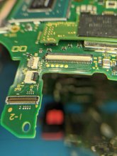
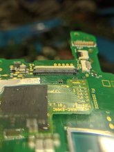
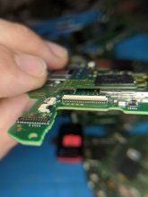
ya it does good job, so no pads come up on you when you disordered did it? also the connecter could be bad but dont know anyone that gets that unlucky, get your meter out and check fuses and chips leading to that connecter.I think it looks factory
ya it does good job, so no pads come up on you when you disordered did it? also the connecter could be bad but dont know anyone that gets that unlucky, get your meter out and check fuses and chips leading to that connecter.
That's why I'm here. I'm not sure which ones drive it. Thanks
Check p13usb video chip, could have a short when Those pads Crossed
I was under the impression the p13 was just responsible for sending the signal to the tv and if it displays on the tv it should be fine. Either way I'll remove it and see if that changes anything
Thanks for your help

The PI3 purely deals with multiplexing the output over USB Type-C and it's clearly working if you are docking and getting a picture. The M92 does some marshalling of the various modes using three discrete lines. CONF0, 1, 2. I currently believe comms with it is purely one-way via the 3 discrete lines.


Conf0 covers connector orientation (in handheld mode, you could still be charging for example)
Conf1 covers whether it is in dock mode (this sends USB3 + 2 Lane DP over USB Type-C)
Conf2 deals with variations of the number of lanes
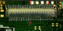
There are occasions when the backlight does come on when it is docked. That's normally to display a charging symbol for example. Sounds like your LCD and backlight are working if you have tried different front assemblies, your soldering looks great on the LCD connector and we know the backlight controller is working as you said you are getting a backlight.
So check Pin 36's test pad to see if it is high when in handheld mode. It shouldn't be.
I know the Tegra monitors these three lines from the M92 as it has to do various other procedures like suppressing screen, showing charge symbol etc.
Hopefully this gives you a steer!
Sheriff.
Conf0 covers connector orientation (in handheld mode, you could still be charging for example)
Conf1 covers whether it is in dock mode (this sends USB3 + 2 Lane DP over USB Type-C)
Conf2 deals with variations of the number of lanes
There are occasions when the backlight does come on when it is docked. That's normally to display a charging symbol for example. Sounds like your LCD and backlight are working if you have tried different front assemblies, your soldering looks great on the LCD connector and we know the backlight controller is working as you said you are getting a backlight.
So check Pin 36's test pad to see if it is high when in handheld mode. It shouldn't be.
I know the Tegra monitors these three lines from the M92 as it has to do various other procedures like suppressing screen, showing charge symbol etc.
Hopefully this gives you a steer!
Sheriff.
The PI3 purely deals with multiplexing the output over USB Type-C and it's clearly working if you are docking and getting a picture. The M92 does some marshalling of the various modes using three discrete lines. CONF0, 1, 2. I currently believe comms with it is purely one-way via the 3 discrete lines.
View attachment 213441
View attachment 213442
Conf0 covers connector orientation (in handheld mode, you could still be charging for example)
Conf1 covers whether it is in dock mode (this sends USB3 + 2 Lane DP over USB Type-C)
Conf2 deals with variations of the number of lanes
There are occasions when the backlight does come on when it is docked. That's normally to display a charging symbol for example. Sounds like your LCD and backlight are working if you have tried different front assemblies, your soldering looks great on the LCD connector and we know the backlight controller is working as you said you are getting a backlight.
So check Pin 36's test pad to see if it is high when in handheld mode. It shouldn't be.
I know the Tegra monitors these three lines from the M92 as it has to do various other procedures like suppressing screen, showing charge symbol etc.
Hopefully this gives you a steer!
Sheriff.
Great info. Thank you.
You were the first person to tell me that the switch is supposed to work without the p13usb and now you are adding another great knowledge on that chip [emoji119]The PI3 purely deals with multiplexing the output over USB Type-C and it's clearly working if you are docking and getting a picture. The M92 does some marshalling of the various modes using three discrete lines. CONF0, 1, 2. I currently believe comms with it is purely one-way via the 3 discrete lines.
View attachment 213441
View attachment 213442
Conf0 covers connector orientation (in handheld mode, you could still be charging for example)
Conf1 covers whether it is in dock mode (this sends USB3 + 2 Lane DP over USB Type-C)
Conf2 deals with variations of the number of lanes
There are occasions when the backlight does come on when it is docked. That's normally to display a charging symbol for example. Sounds like your LCD and backlight are working if you have tried different front assemblies, your soldering looks great on the LCD connector and we know the backlight controller is working as you said you are getting a backlight.
So check Pin 36's test pad to see if it is high when in handheld mode. It shouldn't be.
I know the Tegra monitors these three lines from the M92 as it has to do various other procedures like suppressing screen, showing charge symbol etc.
Hopefully this gives you a steer!
Sheriff.
Sent from my SM-N960U using Tapatalk

I had no luck figuring this one out.Did you get managed?
I have the same Problem, everything works, accept for the screen.
I want to try measure Pin 35,36,38, does anybody know which voltage it should show?

Similar threads
- Replies
- 2
- Views
- 319
- Replies
- 8
- Views
- 2K
- Replies
- 4
- Views
- 1K
- Replies
- 8
- Views
- 1K
Site & Scene News
New Hot Discussed
-
-
58K views
Nintendo Switch firmware 18.0.0 has been released
It's the first Nintendo Switch firmware update of 2024. Made available as of today is system software version 18.0.0, marking a new milestone. According to the patch... -
29K views
GitLab has taken down the Suyu Nintendo Switch emulator
Emulator takedowns continue. Not long after its first release, Suyu emulator has been removed from GitLab via a DMCA takedown. Suyu was a Nintendo Switch emulator... -
21K views
Atmosphere CFW for Switch updated to pre-release version 1.7.0, adds support for firmware 18.0.0
After a couple days of Nintendo releasing their 18.0.0 firmware update, @SciresM releases a brand new update to his Atmosphere NX custom firmware for the Nintendo...by ShadowOne333 94 -
18K views
Wii U and 3DS online services shutting down today, but Pretendo is here to save the day
Today, April 8th, 2024, at 4PM PT, marks the day in which Nintendo permanently ends support for both the 3DS and the Wii U online services, which include co-op play...by ShadowOne333 176 -
15K views
GBAtemp Exclusive Introducing tempBOT AI - your new virtual GBAtemp companion and aide (April Fools)
Hello, GBAtemp members! After a prolonged absence, I am delighted to announce my return and upgraded form to you today... Introducing tempBOT AI 🤖 As the embodiment... -
12K views
Pokemon fangame hosting website "Relic Castle" taken down by The Pokemon Company
Yet another casualty goes down in the never-ending battle of copyright enforcement, and this time, it hit a big website which was the host for many fangames based and...by ShadowOne333 65 -
11K views
MisterFPGA has been updated to include an official release for its Nintendo 64 core
The highly popular and accurate FPGA hardware, MisterFGPA, has received today a brand new update with a long-awaited feature, or rather, a new core for hardcore...by ShadowOne333 51 -
11K views
Apple is being sued for antitrust violations by the Department of Justice of the US
The 2nd biggest technology company in the world, Apple, is being sued by none other than the Department of Justice of the United States, filed for antitrust...by ShadowOne333 80 -
10K views
The first retro emulator hits Apple's App Store, but you should probably avoid it
With Apple having recently updated their guidelines for the App Store, iOS users have been left to speculate on specific wording and whether retro emulators as we... -
9K views
"TMNT: The Hyperstone Heist" for the SEGA Genesis / Mega Drive gets a brand new DX romhack with new features
The romhacking community is always a source for new ways to play retro games, from completely new levels or stages, characters, quality of life improvements, to flat...by ShadowOne333 36
-
-
-
223 replies
Nintendo Switch firmware 18.0.0 has been released
It's the first Nintendo Switch firmware update of 2024. Made available as of today is system software version 18.0.0, marking a new milestone. According to the patch...by Chary -
176 replies
Wii U and 3DS online services shutting down today, but Pretendo is here to save the day
Today, April 8th, 2024, at 4PM PT, marks the day in which Nintendo permanently ends support for both the 3DS and the Wii U online services, which include co-op play...by ShadowOne333 -
169 replies
GBAtemp Exclusive Introducing tempBOT AI - your new virtual GBAtemp companion and aide (April Fools)
Hello, GBAtemp members! After a prolonged absence, I am delighted to announce my return and upgraded form to you today... Introducing tempBOT AI 🤖 As the embodiment...by tempBOT -
146 replies
GitLab has taken down the Suyu Nintendo Switch emulator
Emulator takedowns continue. Not long after its first release, Suyu emulator has been removed from GitLab via a DMCA takedown. Suyu was a Nintendo Switch emulator...by Chary -
96 replies
The first retro emulator hits Apple's App Store, but you should probably avoid it
With Apple having recently updated their guidelines for the App Store, iOS users have been left to speculate on specific wording and whether retro emulators as we...by Scarlet -
94 replies
Atmosphere CFW for Switch updated to pre-release version 1.7.0, adds support for firmware 18.0.0
After a couple days of Nintendo releasing their 18.0.0 firmware update, @SciresM releases a brand new update to his Atmosphere NX custom firmware for the Nintendo...by ShadowOne333 -
80 replies
Apple is being sued for antitrust violations by the Department of Justice of the US
The 2nd biggest technology company in the world, Apple, is being sued by none other than the Department of Justice of the United States, filed for antitrust...by ShadowOne333 -
77 replies
Delta emulator now available on the App Store for iOS
The time has finally come, and after many, many years (if not decades) of Apple users having to side load emulator apps into their iOS devices through unofficial...by ShadowOne333 -
65 replies
Pokemon fangame hosting website "Relic Castle" taken down by The Pokemon Company
Yet another casualty goes down in the never-ending battle of copyright enforcement, and this time, it hit a big website which was the host for many fangames based and...by ShadowOne333 -
53 replies
Nintendo "Indie World" stream announced for April 17th, 2024
Nintendo has recently announced through their social media accounts that a new Indie World stream will be airing tomorrow, scheduled for April 17th, 2024 at 7 a.m. PT...by ShadowOne333
-
Popular threads in this forum
General chit-chat
-
 Xdqwerty
Loading…what are you looking at?
Xdqwerty
Loading…what are you looking at?
-
-
-
-
-
-
-
-
-
-
@
Xdqwerty:
@realtimesave, hey there buddy chum pal friend buddy pal chum bud friend fella bruther amigo pal buddy friend chummy chum chum pal
-
@
Xdqwerty:
@realtimesave, hey there buddy chum pal friend buddy pal chum bud friend fella bruther amigo pal buddy friend chummy chum chum pal
-
-
-
-
-
-
-
-
-
-
-
 @
Sicklyboy:
@Xdqwerty, Osu! Tatakae! Ouendan! is the Japanese version of the game, different settings/characters/songs but otherwise identical mechanics. I played that before I knew about Elite Beat Agents lol. Both fantastic games https://en.wikipedia.org/wiki/Osu!_Tatakae!_Ouendan+1
@
Sicklyboy:
@Xdqwerty, Osu! Tatakae! Ouendan! is the Japanese version of the game, different settings/characters/songs but otherwise identical mechanics. I played that before I knew about Elite Beat Agents lol. Both fantastic games https://en.wikipedia.org/wiki/Osu!_Tatakae!_Ouendan+1 -
-
-