Hacking Troubles after SwitchBoot Trinket M0 Install... No more USB Data Flow. Assistance appreciated! :)

HarmonyUnited

Member
OP
Newcomer
Joined
Mar 27, 2019
Messages
12
Trophies
0
Age
37
Location
California
XP
125
Country
United States
Hello all,

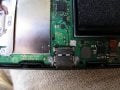
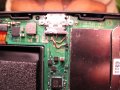
I got inspired to go through with the Trinket M0 modification for the nintendo switch. After many hours I thought I finally got it working until some strange things began to happen. First, I noticed that the volume up strap was electrically stuck as if it was pushed, but mechanically was not. I had a pretty clean install but did manage to accidentally switch D+ and D-, i switched them around and it would deliver the payload... all seemed good. But in troubleshooting the vol+ strap weirdness the system stopped receiving/sending payloads to the RCM switch. I couldn't for the life of me figure it out, thought I fried my trinket or something. Decided to buy another trinket and for the mean time remove all traces of the modification from the motherboard. However, now the switch will not be recognized over usb data lines as the APX or switch in RCM mode. It is definitely going into RCM mode (black screen and not responsive to short pushes of power button)... but the injector wouldnt deliver the payload. I thought, well maybe i fried my injector too. So i used a known worning usb C cable and my computer would not see the RCM switch (APX) either... Im stumped.

I suspect that I damaged or disabled the data lines in my switch somehow? I remember this starting when I disconnected the "USB DISCONNECT STRAP" which is kind of ironic when I think about it now.

The switch DOES:
-Boot to OFW on a clean nand. (was using emuMMC with cfw thankfully), so I can still play the console like a fully functional vanilla switch.
-charge both in the dock and from a usb c cable.
-deliver signal to the HDMI Out port when in docked mode...

SEEMS TO:
-Enter RCM mode with RCM Jig and Power plus Vol+

DOES NOT:
-have auto-rcm enabled
-respond to payload injector or computer payload program
-make me feel warm and fuzzy in my homebrew blanket.

Does anybody have any hints or clues for me? Replace an SMD chip? Other voodoo or jedi tricks out there?
Any help would be SUPER appreciated!! :)

Thanks so much for the help! CHEERS! :)
 
Last edited by HarmonyUnited,

HarmonyUnited

Member
OP
Newcomer
Joined
Mar 27, 2019
Messages
12
Trophies
0
Age
37
Location
California
XP
125
Country
United States
I removed each and every trace of the install... but here are a few photos of the board before i removed all the modifications. This is right after I removed the USB disconnect strap... (as a PS, can anyone explain what this strap actually does in the trinket?)

I noticed that i couldn't use my dongle payload injector when the trinket was hooked up... I thought the connected data lines were messing with the impedance of the D+/- lines. This logic led me to thinking the unit would return to normal USB operation if I just removed those wires... Alas, after removing the modifications, USB functionality for data, at least in RCM mode, did not return.

Thanks for any help :)


SwitchTrinketModBoard.jpg SwitchTrinketModVol+strap.JPG
 
Last edited by HarmonyUnited,

kylum

Well-Known Member
Member
Joined
Dec 8, 2008
Messages
394
Trophies
1
XP
1,481
Country
United States
Go back over the switch motherboard and check for shorts to ground on the data lines. Also look for any possible bridging. Wouldn't hurt to take some high res photos of the board and post them. Do usb only devices work as intended if you have anything you can test, usb controller, Bluetooth dongle, Ethernet adapter...? Volume and power buttons work as intended on OFW, in other words, did you sort out the issue with the volume you were experiencing?
 
Last edited by kylum,

HarmonyUnited

Member
OP
Newcomer
Joined
Mar 27, 2019
Messages
12
Trophies
0
Age
37
Location
California
XP
125
Country
United States
Go back over the switch motherboard and check for shorts to ground on the data lines. Also look for any possible bridging. Wouldn't hurt to take some high res photos of the board and post them. Do usb only devices work as intended if you have anything you can test, usb controller, Bluetooth dongle, Ethernet adapter...? Volume and power buttons work as intended on OFW, in other words, did you sort out the issue with the volume you were experiencing?

Thanks for the advice. I will give it a try... the only place it could be bridging are the D+/- test points directly above the USB-C port. I will have to check that when I'm back from my trip. I will have to check the USB device deali-o... I do know that it charges through usb cable and when docked... also transmits display data for the HDMI over the dock usb c. Devices? Not sure yet.

As for the volume up strap? I did not sort that out with the trinket installed. If I disconnected the volume up strap from the trinket it would not happen; the volume at this point would be fine in OFW. But if the vol strap was connected to the M0 the OFW would still be receiving a continuous "turn the volume up" command. Its possible something was wrong with the trinket itself. But there were too many factors at play to nail it down for sure. I think the trinket was somehow pulling the volume strap to ground all the time. I am sure that it was on the correct pad on the M0. re:wiring - I was definitely connected to pad 0 and my switch solder point was the "alt volume strap" point on the corner of the little button switch assembly at the end of the ribbon cable (not on the motherboard itself.)The issue was that the trinket would just go into bootloader drive mode whenever I would try to boot because it thought I was holding it down for more than 15 seconds. So with this much information i know that there doesnt seem to be an issue with the buttons themselves on the switch console; seems its in the trinket or my wiring...

Anyway, thanks so much for the responses! We will figure this out im sure :)
 

HarmonyUnited

Member
OP
Newcomer
Joined
Mar 27, 2019
Messages
12
Trophies
0
Age
37
Location
California
XP
125
Country
United States
@kylum : I checked the board for shorts on d+/- at the place where the test pins are above the usb port. Nothing bridged. During the modification process I did, however, damage the right test pad and it came up off of the board... i ended up just scratching the little trace above it and soldered the trinket wire there and it did work for a bit. Is the test pad there in the middle of a trace or just at the end of the line? Like did I break a continuity that should be there? I have not tested trying to inject on the back side of the motherboard yet. Ideas?

I also just tested a USB only device. My bluetooth audio dongle gets powered but doesn't transmit audio... The switch used to change to "USB AUDIO" mode but just stays on internal speakers... definitely something up with the data lines... hmmmm
 
Last edited by HarmonyUnited,

kylum

Well-Known Member
Member
Joined
Dec 8, 2008
Messages
394
Trophies
1
XP
1,481
Country
United States
@kylum : I checked the board for shorts on d+/- at the place where the test pins are above the usb port. Nothing bridged. During the modification process I did, however, damage the right test pad and it came up off of the board... i ended up just scratching the little trace above it and soldered the trinket wire there and it did work for a bit. Is the test pad there in the middle of a trace or just at the end of the line? Like did I break a continuity that should be there? I have not tested trying to inject on the back side of the motherboard yet. Ideas?

I also just tested a USB only device. My bluetooth audio dongle gets powered but doesn't transmit audio... The switch used to change to "USB AUDIO" mode but just stays on internal speakers... definitely something up with the data lines... hmmmm
Looking at the test pads on @mattytrog ‘s install post it does look like they are end of line but not entirely sure of that. Maybe you previously had a short there and it caused other damage to the usb data lines else where or when you had them swapped it caused damage. I would assume there is a damaged IC or other component if the pad is indeed end of line. Hopefully Matty will see this and be able to assist you in finding the issue.
 

mattytrog

You don`t want to listen to anything I say.
Member
Joined
Apr 27, 2018
Messages
3,708
Trophies
0
Age
48
XP
4,328
Country
United Kingdom
OK...

Lets see... Damaged right hand pad.

Easily fixed if you have decent iron tip... Graphic to follow...

--------------------- MERGED ---------------------------

altpads.jpg


You ofcourse only need to do the blue one.
 
  • Like
Reactions: kylum

HarmonyUnited

Member
OP
Newcomer
Joined
Mar 27, 2019
Messages
12
Trophies
0
Age
37
Location
California
XP
125
Country
United States
Ok matty, I tried just the blue one... no fix. Then both, still nothing. checked continuity from usb pins to the places you showed me and they are definitely connected... I couldnt get at the little leg of that 6 legged thing where the blue and yellow were attached to. But i noticed the pad was still connected to that leg... but the pad was not connected to the usb c port line. Now the port is connected to those points electrically. But no go...

(the light angle makes my board look filthy... maybe it is but it doesn't seem so to the naked eye)

What do you think is the next step?
 

Attachments

  • IMG_0281.JPG
    IMG_0281.JPG
    1.3 MB · Views: 317

mattytrog

You don`t want to listen to anything I say.
Member
Joined
Apr 27, 2018
Messages
3,708
Trophies
0
Age
48
XP
4,328
Country
United Kingdom
Ok matty, I tried just the blue one... no fix. Then both, still nothing. checked continuity from usb pins to the places you showed me and they are definitely connected... I couldnt get at the little leg of that 6 legged thing where the blue and yellow were attached to. But i noticed the pad was still connected to that leg... but the pad was not connected to the usb c port line. Now the port is connected to those points electrically. But no go...

(the light angle makes my board look filthy... maybe it is but it doesn't seem so to the naked eye)

What do you think is the next step?

OK You only needed to do the blue one.

Also it looks like the copper wire might be touching another testpoint and it doesn`t look "square" on the pin.

Check you have continuity through the inline filter(the tiny square thing just above / below the extra filter you have soldered to)
 

Site & Scene News

Popular threads in this forum

General chit-chat
Help Users
    Xdqwerty @ Xdqwerty: Hi +1