Hardware TV mode and USB is not working after P13USB replacement

Agilato

Well-Known Member
Member
Joined
Jun 21, 2019
Messages
361
Trophies
0
Age
35
XP
693
Country
United States
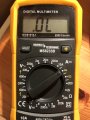
I've checked the USB port and got these values:

Red pin on GND and black one on USB port pins:
0,0, OL, OL, 1120, OL, OL, OL, .523, 1120, OL, OL, 0,0

Black pin on GND and red one on USB port pins:
0,0, OL, OL, OL, OL, OL, OL, 1300, OL, OL, OL, 0,0

These are the reference values from the video:
G, OL, OL, .467, .718, .754, .755, .494, .467, OL, OL, G

So I guess the port is broken. It looks soldered properly but maybe it's just faulty. I'll replace it after work :D

You have to test it in DIODE mode.
 
  • Like
Reactions: FXDX

seidolino

Well-Known Member
OP
Newcomer
Joined
Jan 29, 2020
Messages
63
Trophies
0
Age
34
XP
344
Country
Austria
I tested it using DIODE mode, are the values that strange? another board which I've tested shows nearly the reference values from the video, so I guess the usb is faulty.
 

Attachments

  • IMG_9557.JPG
    IMG_9557.JPG
    1.2 MB · Views: 368

Agilato

Well-Known Member
Member
Joined
Jun 21, 2019
Messages
361
Trophies
0
Age
35
XP
693
Country
United States
I tested it using DIODE mode, are the values that strange? another board which I've tested shows nearly the reference values from the video, so I guess the usb is faulty.

I would remove USB-C port, check each pin write values, put new one and make sure it's the same.
Problem is that with wires over filters you might have slight different values than in video.
 
  • Like
Reactions: FXDX

seidolino

Well-Known Member
OP
Newcomer
Joined
Jan 29, 2020
Messages
63
Trophies
0
Age
34
XP
344
Country
Austria
@Agilato I removed the USB port and checked all the pins, that's the result:

G OL OL .483 .782 .875 .108 .487 .504 OL OL G

after I soldered a new port onto the board I checked all pins again and the values were nearly the same. The board is charging but there is still no usb/hdmi connection..
 
  • Like
Reactions: Agilato

Agilato

Well-Known Member
Member
Joined
Jun 21, 2019
Messages
361
Trophies
0
Age
35
XP
693
Country
United States
So, let me summarize:
  • Port got replaced 3 times
  • All chokes are good and read thru without shoring lines to each-other inside of element and to the ground
  • All capacitors on place
  • All resistors on all P13USB lines in tact?
 
Last edited by Agilato,
  • Like
Reactions: FXDX

FXDX

Well-Known Member
Member
Joined
Sep 15, 2019
Messages
325
Trophies
0
XP
1,989
Country
Dominican Republic
@Agilato I removed the USB port and checked all the pins, that's the result:

G OL OL .483 .782 .875 .108 .487 .504 OL OL G

after I soldered a new port onto the board I checked all pins again and the values were nearly the same. The board is charging but there is still no usb/hdmi connection..

After all you've tried and the problem still persists no usb / hdmi connection, then there may be something wrong with the connections under the Tegra SoC.
 

FXDX

Well-Known Member
Member
Joined
Sep 15, 2019
Messages
325
Trophies
0
XP
1,989
Country
Dominican Republic
@FXDX Do you think it will be possible in his case to reflow Tegra SoC instead of reballing ?
Did you do reflow to MAX77620 and no change?
You can try a reflow to Tegra SoC but be careful. Fux quality and air station at 320 degrees maximum and with moderate air flow. Do not keep the nozzle very close to the processor. See if anything changes.
 

SlegBE

Well-Known Member
Newcomer
Joined
Jan 17, 2020
Messages
53
Trophies
0
Age
46
XP
152
Country
Belgium
Hey I m not Sedolino ;)

But I have exactly the same problem.
I will try to reflow MAX77620 today and let you know if it will be a success... or not :)

Maybe @sedolino will do the job before me.
 
  • Like
Reactions: FXDX

SlegBE

Well-Known Member
Newcomer
Joined
Jan 17, 2020
Messages
53
Trophies
0
Age
46
XP
152
Country
Belgium
Hmm I've tried to reflow MAX but no improvement. But I'm not sure the reflow has been effective because the chip has not slightly move during the process. I was afraid to break it with a high temperature. So I started with 320 degrees during one minute and after 370 for the 2nd and last minute.
Usually I use 400degrees to remove a chip...
 
  • Like
Reactions: FXDX

FXDX

Well-Known Member
Member
Joined
Sep 15, 2019
Messages
325
Trophies
0
XP
1,989
Country
Dominican Republic
Hmm I've tried to reflow MAX but no improvement. But I'm not sure the reflow has been effective because the chip has not slightly move during the process. I was afraid to break it with a high temperature. So I started with 320 degrees during one minute and after 370 for the 2nd and last minute.
Usually I use 400degrees to remove a chip...
When it reaches the melting point, you should if you slightly touch it with a tweezers the chip will move a little. Then you are sure of a successful reflow.
The flux used matters a lot and the temperature and the process used, but I think that you know and have done.
 
Last edited by FXDX,

SlegBE

Well-Known Member
Newcomer
Joined
Jan 17, 2020
Messages
53
Trophies
0
Age
46
XP
152
Country
Belgium
Hello,

I don't want to give up for this kind of problem and I should confirm like @FXDX said that this kind of issue is probably caused by problem under Tegra SoC.

In my case, I found that RX1+/RX1- and RX2+/RX2- have no value in diode mode and if you look at the block diagram attached, you will see that in front of RX1 and RX2 you will find DP3+-, RX+- and DP0+-

And if you follow the end of tracks for these pins (excepted for DP3 I don't see anything) you will see that there are located under the Tegra Soc.

I think the only liable way to solve this issue is to reball the SoC.

I highly hesitate to reflow it because I'm not equiped for this work (Yihua 852D) and should destroy the SoC.

So I'm asking for a price request for a reballing in Belgium... and if it is not too expensive I will of course let you know if it solve the issue.


Capture.PNG

IMG_1681[1].JPG
 
  • Like
Reactions: FXDX

seidolino

Well-Known Member
OP
Newcomer
Joined
Jan 29, 2020
Messages
63
Trophies
0
Age
34
XP
344
Country
Austria
hey guys! a friend of mine found the cause of the problem. the solder joint of this resistor next to the USB IC was broken. I don't know why I didn't see that, but now USB as well as HDMI are working again :bow: thanks a lot for your contribution to this topic!
 

Attachments

  • broken-solder-joint.jpeg
    broken-solder-joint.jpeg
    126.1 KB · Views: 436
  • Like
Reactions: FXDX

SlegBE

Well-Known Member
Newcomer
Joined
Jan 17, 2020
Messages
53
Trophies
0
Age
46
XP
152
Country
Belgium
Hello,

I don't want to give up for this kind of problem and I should confirm like @FXDX said that this kind of issue is probably caused by problem under Tegra SoC.

In my case, I found that RX1+/RX1- and RX2+/RX2- have no value in diode mode and if you look at the block diagram attached, you will see that in front of RX1 and RX2 you will find DP3+-, RX+- and DP0+-

And if you follow the end of tracks for these pins (excepted for DP3 I don't see anything) you will see that there are located under the Tegra Soc.

I think the only liable way to solve this issue is to reball the SoC.

I highly hesitate to reflow it because I'm not equiped for this work (Yihua 852D) and should destroy the SoC.

So I'm asking for a price request for a reballing in Belgium... and if it is not too expensive I will of course let you know if it solve the issue.


View attachment 197495
View attachment 197496

Arf, price offer received for a reballing... 99€.

I attempted to reflow CPU using my hot airgun at 320° during 5min and ... stopped because I fear to not have the good method and could damage something on the top of cpu.
I don't have a preheater...
 

YakkunNet

New Member
Newbie
Joined
Dec 24, 2009
Messages
3
Trophies
0
XP
1
Country
Hi, I am having a problem similar to the one discussed in this thread.
My Nintendo Switch had a problem with not charging, I replaced the TypeC connector and now it charges on both sides. (I accidentally damaged the pad when replacing it, so I repaired it with enameled wire.) When I connect the Switch to my PC, it is correctly recognized as a USB device, but I cannot output HDMI at 720p or 1080p. It is possible to output video at 480p, but it is very unstable.
The TypeC connector diodes all show the expected values, so if it's not due to bad contact with the TypeC, what could be the cause?
There have been several threads discussing HDMI choke coil failure. My choke coil is showing continuity on both sides. Is it possible that the choke coil is damaged even though it shows continuity? If so, is there a better way to test the choke coil?

Thanks in advance.
 

jkyoho

Well-Known Member
Member
Joined
Sep 2, 2020
Messages
1,248
Trophies
0
Age
39
Location
TORONTO
Website
form.jotform.com
XP
2,187
Country
Canada
Hi, I am having a problem similar to the one discussed in this thread.
My Nintendo Switch had a problem with not charging, I replaced the TypeC connector and now it charges on both sides. (I accidentally damaged the pad when replacing it, so I repaired it with enameled wire.) When I connect the Switch to my PC, it is correctly recognized as a USB device, but I cannot output HDMI at 720p or 1080p. It is possible to output video at 480p, but it is very unstable.
The TypeC connector diodes all show the expected values, so if it's not due to bad contact with the TypeC, what could be the cause?
There have been several threads discussing HDMI choke coil failure. My choke coil is showing continuity on both sides. Is it possible that the choke coil is damaged even though it shows continuity? If so, is there a better way to test the choke coil?

Thanks in advance.
did you test the hidden rail of usb port pins? since pins on hidden rail are more to usb for hdmi output, breakout board helps a lot to diagnose type-c replacement work good or not.
Choke coil filter normally go bad when no continuity, so I think you have other issue not the coils
 

YakkunNet

New Member
Newbie
Joined
Dec 24, 2009
Messages
3
Trophies
0
XP
1
Country
did you test the hidden rail of usb port pins? since pins on hidden rail are more to usb for hdmi output, breakout board helps a lot to diagnose type-c replacement work good or not.
Choke coil filter normally go bad when no continuity, so I think you have other issue not the coils

Thank you for your reply.
Yes, I have USB-C breakout board, and I have checked connectivity according to the @FXDX post. All pins are correctly connected.
If coil is not broken because there is continuity, what else could be the problem?
 

Attachments

  • connection.png
    connection.png
    2.3 MB · Views: 286

jkyoho

Well-Known Member
Member
Joined
Sep 2, 2020
Messages
1,248
Trophies
0
Age
39
Location
TORONTO
Website
form.jotform.com
XP
2,187
Country
Canada
check pi3usb ic pins diode value to see any of those is huge different. Then maybe replace a new pi3usb ic or heat it up 150c to see anything change
 

Attachments

  • pi3usb diode.png
    pi3usb diode.png
    31.7 KB · Views: 321

Site & Scene News

Popular threads in this forum

General chit-chat
Help Users
    Psionic Roshambo @ Psionic Roshambo: https://youtu.be/hYkEl-3x92A?si=JSDoEc2QCDOrtimz