Hardware TV mode and USB is not working after P13USB replacement

seidolino

Well-Known Member
OP
Newcomer
Joined
Jan 29, 2020
Messages
63
Trophies
0
Age
34
XP
344
Country
Austria
hey guys!

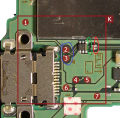
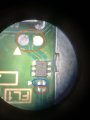
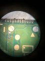
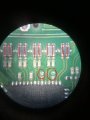
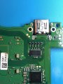
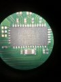
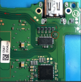
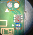
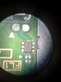
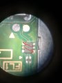
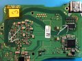
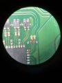
I'm facing a strange issue with one of my switches. Initially the switch wasn't able to boot at all until a friend of mine removed the P13USB IC. Afterwards the switch was able to start, it can be used in handheld mode without any problems and it's charging. Then I ordered a new USB IC and soldered it onto the board. It boots with this new chip but the output to the TV as well as USB connection to the PC isn't working. I've checked the EXC-24CS350U around the USB IC and one of them was damaged so I placed a jumper on this component, so that it works as the others. Then I noticed that the cap/fuse near the USB C port wasn't working. I replaced it but still no HDMI or USB connection. Does anyone have any idea what the problem might be? FYI: I tried 5 different P13USB IC's just to make sure it's not the chip. Maybe it's also related to my soldering skills. Can I somehow check if the USB IC is soldered correctly?

thanks!!
 

SlegBE

Well-Known Member
Newcomer
Joined
Jan 17, 2020
Messages
53
Trophies
0
Age
46
XP
152
Country
Belgium
Can you also check the continuity of this filter ?
 

Attachments

  • Capture.PNG
    Capture.PNG
    1.1 MB · Views: 891

seidolino

Well-Known Member
OP
Newcomer
Joined
Jan 29, 2020
Messages
63
Trophies
0
Age
34
XP
344
Country
Austria
@SlegBE : we had to remove this component too, we added two jumpers (picture nr.1) and continuity is given. by the way, do you know the part number? :-)

@Agilato :

Picture nr 2: we had to replace the filter with a jumper, but continuity is given there as well
Picture nr 3: as you can see continuity is given for the parts above the usb ic as well and we removed these two caps since we needed those for a different board which has the same symptoms. but hdmi wasn't working when they were in place.
Picture nr 4: just an overview
Picture nr 5: the P13USB ic itself
 

Attachments

  • 1.jpg
    1.jpg
    581 KB · Views: 704
  • 2.jpg
    2.jpg
    553.8 KB · Views: 607
  • 3.jpg
    3.jpg
    600.1 KB · Views: 719
  • 4.JPG
    4.JPG
    943.1 KB · Views: 624
  • 5.JPG
    5.JPG
    931 KB · Views: 602
Last edited by seidolino,

Agilato

Well-Known Member
Member
Joined
Jun 21, 2019
Messages
361
Trophies
0
Age
35
XP
693
Country
United States
@SlegBE : we had to remove this component too, we added two jumpers (picture nr.1) and continuity is given. by the way, do you know the part number? :-)

@Agilato :

Picture nr 2: we had to replace the filter with a jumper, but continuity is given there as well
Picture nr 3: as you can see continuity is given for the parts above the usb ic as well and we removed these two caps since we needed those for a different board which has the same symptoms. but hdmi wasn't working when they were in place.
Picture nr 4: just an overview
Picture nr 5: the P13USB ic itself

You have to put caps back and test stuff i circled also check two resistors near CPU by lines i pointed.

Filter on the other side that you replaced with wires goes directly to SOC and if you don't have any life on PC mostly no way to fix it, check diode filter it should't have any continuity i pointed, it might ground signals(console should work fine without it, just remove it to test)

Also no matter how good you are with USB-C port replacement some times you have to do it twice, always a change you under heat it.
 

Attachments

  • Capture.PNG
    Capture.PNG
    1,022 KB · Views: 642
  • Capture1.PNG
    Capture1.PNG
    687.3 KB · Views: 563
Last edited by Agilato,
  • Like
Reactions: FXDX

seidolino

Well-Known Member
OP
Newcomer
Joined
Jan 29, 2020
Messages
63
Trophies
0
Age
34
XP
344
Country
Austria
thanks for the quick replies!! ok, I'll reinstall the caps :-) I've checked the following things:

image 6: this component goes to ground on these pins
image 7: there is no continuity in these directions
image 8: there is continuity in these directions
image 9: yellow: the pads where there is continuity to the filters on the board; red: no continuity to the caps on the other side of the board

--------------------- MERGED ---------------------------

my colleague replaced the USB port, it was charging but no HDMI. then I replaced it with a new one and again charging but no HDMI :-(
 

Attachments

  • 6.jpg
    6.jpg
    572.7 KB · Views: 540
  • 7.jpg
    7.jpg
    573.6 KB · Views: 479
  • 8.jpg
    8.jpg
    818.3 KB · Views: 625
  • 9.jpg
    9.jpg
    543.7 KB · Views: 543

Agilato

Well-Known Member
Member
Joined
Jun 21, 2019
Messages
361
Trophies
0
Age
35
XP
693
Country
United States
thanks for the quick replies!! ok, I'll reinstall the caps :-) I've checked the following things:
image 9: yellow: the pads where there is continuity to the filters on the board; red: no continuity to the caps on the other side of the board

You shouldn't have direct continuity thru caps those are smoothing one, just make sure they are ok and also check if resistors are good.
 
  • Like
Reactions: FXDX

seidolino

Well-Known Member
OP
Newcomer
Joined
Jan 29, 2020
Messages
63
Trophies
0
Age
34
XP
344
Country
Austria
ok, there is no direct continuity, there is no continuity regardless which direction :-) sorry but how can I check if the resistors are good? I'm not a pro :unsure:
 

Agilato

Well-Known Member
Member
Joined
Jun 21, 2019
Messages
361
Trophies
0
Age
35
XP
693
Country
United States
Check actual resistance(Ω) of the resistors, if you aren't reading any value it's mostly dead, you should have around 10-100k on those.
 
  • Like
Reactions: FXDX

FXDX

Well-Known Member
Member
Joined
Sep 15, 2019
Messages
325
Trophies
0
XP
1,989
Country
Dominican Republic
@SlegBE : we had to remove this component too, we added two jumpers (picture nr.1) and continuity is given. by the way, do you know the part number? :-)

Picture nr 2: we had to replace the filter with a jumper, but continuity is given there as well

It seems that it is not a simple fuse and in fact it is a resistor that would reduce the voltage from 5v to 3.2v. It would be good to replace it with a good one from the donor plate.

2..jpg 2.jpg
 
Last edited by FXDX,

Agilato

Well-Known Member
Member
Joined
Jun 21, 2019
Messages
361
Trophies
0
Age
35
XP
693
Country
United States
It seems that it is not a simple fuse and in fact it is a resistor that would reduce the voltage from 5v to 3.2v. It would be good to replace it with a good one from the donor plate.

View attachment 194745 View attachment 194744

Disagree with that being a non regular fuse.
I have 5v or 15v on each side of the fuse with my other working boards, dependence on what charger i use.
Also i have 2 switches working well 100% with no fuse, with blob of solder.
 
Last edited by Agilato,
  • Like
Reactions: FXDX

FXDX

Well-Known Member
Member
Joined
Sep 15, 2019
Messages
325
Trophies
0
XP
1,989
Country
Dominican Republic
@FXDX ok, great! I'll take one from a different board. do you maybe know where I can buy this part? or do you know the part number?
Initially, so I thought it was a fuse and it seems to be that, but as i wrote, i read on a forum where someone with advanced knowledge in electronics said that it is actually a resistor.
Something that would work is here but i don't know if that's exactly what you need.
Size it’s 0402, 2.5-3.5A 32V
https://ro.mouser.com/ProductDetail…xU2g/1juGqWJziY9CkRY0q3bf57mmt23FjtSoMtlV0Q==

@Agilato
If it goes with a bridge then it is perfect!:grog:
 
Last edited by FXDX,

Agilato

Well-Known Member
Member
Joined
Jun 21, 2019
Messages
361
Trophies
0
Age
35
XP
693
Country
United States
Initially, so I thought it was a fuse and it seems to be that, but as i wrote, i read on a forum where someone with advanced knowledge in electronics said that it is actually a resistor.
Something that would work is here but i don't know if that's exactly what you need.
Size it’s 0402, 2.5-3.5A 32V
https://ro.mouser.com/ProductDetail…xU2g/1juGqWJziY9CkRY0q3bf57mmt23FjtSoMtlV0Q==

It's 0 ohm resistor used as fuse, very common situation in very sensitive places because they fuse very quickly and without making a mess.
 
Last edited by Agilato,
  • Like
Reactions: jkyoho and FXDX

seidolino

Well-Known Member
OP
Newcomer
Joined
Jan 29, 2020
Messages
63
Trophies
0
Age
34
XP
344
Country
Austria
ok, thanks for the info! do you guys have any other ideas why the USB connection isn't working? I checked the resistors around the P13USB as well as the caps there, am I missing something?
 

seidolino

Well-Known Member
OP
Newcomer
Joined
Jan 29, 2020
Messages
63
Trophies
0
Age
34
XP
344
Country
Austria
is it maybe possible to check if the USB IC and the USB port are soldered properly? some values on certain pins or anything similar?
 

seidolino

Well-Known Member
OP
Newcomer
Joined
Jan 29, 2020
Messages
63
Trophies
0
Age
34
XP
344
Country
Austria
I've checked the USB port and got these values:

Red pin on GND and black one on USB port pins:
0,0, OL, OL, 1120, OL, OL, OL, .523, 1120, OL, OL, 0,0

Black pin on GND and red one on USB port pins:
0,0, OL, OL, OL, OL, OL, OL, 1300, OL, OL, OL, 0,0

These are the reference values from the video:
G, OL, OL, .467, .718, .754, .755, .494, .467, OL, OL, G

So I guess the port is broken. It looks soldered properly but maybe it's just faulty. I'll replace it after work :D
 
  • Like
Reactions: Ericthegreat

Site & Scene News

Popular threads in this forum

General chit-chat
Help Users
  • No one is chatting at the moment.
    AncientBoi @ AncientBoi: :rofl2: +1