Hardware M92T36 or BQ24193

Pintglass

Well-Known Member
Member
Joined
Jan 28, 2019
Messages
364
Trophies
0
Age
52
XP
782
Country
United Kingdom
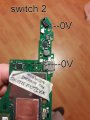
While attempting to make measures on my working motherboard, I've shorted pin A5 with A4 from USB while Adpter Plugged. Result : now I have 2 motherboard that works, run in RCM and EmuMMC works...but doesn't charge. Both of them show on Battery Info on Hekate 1000mh (tested with 2 different battery). No voltage arrive on Battery pin for charging.

I've read all post here...and I believe my problem should be on the BQ...can this is possible?

If your sure you've shorted A4 and A5 its more than likely the M92T36 that will be the issue.
 

MAST3RF0X

Member
Newcomer
Joined
Feb 20, 2017
Messages
24
Trophies
0
Age
43
Website
www.mypizzatube.com
XP
147
Country
Italy
If your sure you've shorted A4 and A5 its more than likely the M92T36 that will be the issue.
Thank you for your fast reply. There is a way to check this chip or the only way is to replace it?

Some Update
Switch 1 (the one faulty where I've replace cap): Hakate Works, Battery Info says 1000Mah. Start in every way (CFWNand, CFWEemu and Sysnand). The only thing that doesn't work is charging. Usb Port from Pc, Adpter or Dock (blinking) doesn't charge. What should I check?

Switch 2 (the one I've shorted A4 to A5, before was full working) :
Hakate Works, Battery Info says 1000Mah. Sysnand Start show error 2110-0001 (something like this), CfwNand doesn't start, EmuNand doesn't tried. Now doesn't charge anymore.

Some Idea to check before I will try a chip replace (not quite sure which chip to replace yet)?
 

Pintglass

Well-Known Member
Member
Joined
Jan 28, 2019
Messages
364
Trophies
0
Age
52
XP
782
Country
United Kingdom
Thank you for your fast reply. There is a way to check this chip or the only way is to replace it?

Some Update
Switch 1 (the one faulty where I've replace cap):
Hakate Works, Battery Info says 1000Mah. Start in every way (CFWNand, CFWEemu and Sysnand). The only thing that doesn't work is charging. Usb Port from Pc, Adpter or Dock (blinking) doesn't charge. What should I check?

Switch 2 (the one I've shorted A4 to A5, before was full working) :
Hakate Works, Battery Info says 1000Mah. Sysnand Start show error 2110-0001 (something like this), CfwNand doesn't start, EmuNand doesn't tried. Now doesn't charge anymore.

Some Idea to check before I will try a chip replace (not quite sure which chip to replace yet)?

What voltage do you get on pin 1 of BQ24193 with the charger plugged in.
 

MAST3RF0X

Member
Newcomer
Joined
Feb 20, 2017
Messages
24
Trophies
0
Age
43
Website
www.mypizzatube.com
XP
147
Country
Italy
Here the voltage I can see..
Switch 1 is the working one but not charging
Switch 2 is my switch where I shorted out something....(was working, now not anymore)
Both works with Hakate

Thank you a lot for your support.
 

Attachments

  • 20191228_184845.jpg
    20191228_184845.jpg
    1.4 MB · Views: 511
  • 20191228_184831.jpg
    20191228_184831.jpg
    861.9 KB · Views: 570

Agilato

Well-Known Member
Member
Joined
Jun 21, 2019
Messages
361
Trophies
0
Age
35
XP
693
Country
United States
In Switch 1 You have to check caps on short near m92t36 chip and voltage on 5 and 6th pins of it when supply connected.
Switch 2 with 0 volts on this pad doesn't make any sense ofc only if this line fully aren't shorted to ground and power supply goes in safe mode, but in this case you should have blown fuse right near that pad.
 
  • Like
Reactions: FXDX

Pintglass

Well-Known Member
Member
Joined
Jan 28, 2019
Messages
364
Trophies
0
Age
52
XP
782
Country
United Kingdom
Here the voltage I can see..
Switch 1 is the working one but not charging
Switch 2 is my switch where I shorted out something....(was working, now not anymore)
Both works with Hakate

Thank you a lot for your support.

Have you tested with the battery connected?

Can you not test pin 1 of BQ24193?
 
  • Like
Reactions: FXDX

MAST3RF0X

Member
Newcomer
Joined
Feb 20, 2017
Messages
24
Trophies
0
Age
43
Website
www.mypizzatube.com
XP
147
Country
Italy
...wait...I've changed Power Supply...measuring

Measures Update : Check Images

Switch 1 : black fuse just over the USB port is shorted?
Switch 2 : just discovered it measure 5V only on one side of USBC (if cabled turned doesn't work)

I've tested all Caps in Diode mode on both motherboards and all show the same value (mostly 0.380)
 

Attachments

  • Switch 1.jpg
    Switch 1.jpg
    988 KB · Views: 516
  • Switch 2_test (0-00-00-00).jpg
    Switch 2_test (0-00-00-00).jpg
    955.6 KB · Views: 764
Last edited by MAST3RF0X,

Pintglass

Well-Known Member
Member
Joined
Jan 28, 2019
Messages
364
Trophies
0
Age
52
XP
782
Country
United Kingdom
The black component just above the usb port is a fuse, it should have 5V on both sides.

This is based on what you've got in the images as your saying the opposite

Check the fuse for continuity on the switch with only 0.3v on the top side, and check the small cap on pin 9 of M92T36 for a short to ground.


I'd say you have a faulty M92T36 on the 2nd switch so change that.
 
Last edited by Pintglass,
  • Like
Reactions: FXDX

MAST3RF0X

Member
Newcomer
Joined
Feb 20, 2017
Messages
24
Trophies
0
Age
43
Website
www.mypizzatube.com
XP
147
Country
Italy
The black component just above the usb port is a fuse, it should have 5V on both sides.

This is based on what you've got in the images as your saying the opposite

Check the fuse for continuity on the switch with only 0.3v on the top side, and check the small cap on pin 9 of M92T36 for a short to ground.


I'd say you have a faulty M92T36's on the 2nd switch so change that.

Yep...edited past post to better understand.

So seems Switch 1 have the fuse gone (could be only this??). How I should change / repair it? small cap at Pin9 is working fine (same value as Switch 2, little difference 0.3 but they are quite little different seems)

And Switch 2 ... I've read M92T36 can go if recive more than 6v (maybe the short i've done with USB pin...). There is a way to test it before removing?

Thank again for your support. Really I'm having a lot of fun studying those two motherboard.
 

Pintglass

Well-Known Member
Member
Joined
Jan 28, 2019
Messages
364
Trophies
0
Age
52
XP
782
Country
United Kingdom
Yep...edited past post to better understand.

So seems Switch 1 have the fuse gone (could be only this??). How I should change / repair it? small cap at Pin9 is working fine (same value as Switch 2, little difference 0.3 but they are quite little different seems)

And Switch 2 ... I've read M92T36 can go if recive more than 6v (maybe the short i've done with USB pin...). There is a way to test it before removing?

Thank again for your support. Really I'm having a lot of fun studying those two motherboard.

Are you saying the fuse is showing as open line or has continuity on switch 1? is this the switch where you shorted the usb connector pins?

The M92T36 will be your issue on the second switch, you will have to replace it.
 
Last edited by Pintglass,
  • Like
Reactions: FXDX

MAST3RF0X

Member
Newcomer
Joined
Feb 20, 2017
Messages
24
Trophies
0
Age
43
Website
www.mypizzatube.com
XP
147
Country
Italy
Are you saying the fuse is showing as open line or has continuity on switch 1? is this the switch where you shorted the usb connector pins?

The M92T36 will be your issue on the second switch, you will have to replace it.
No I've Shorted the USB Pin on Second Switch (where also I believe the M92T36 was shorted / burned because of this ...)

The Fuse on first Switch act like a wall. In 5V out 0.2V
The Fuse on secondo Switch act like a wire : In 5V out 5V
 

MAST3RF0X

Member
Newcomer
Joined
Feb 20, 2017
Messages
24
Trophies
0
Age
43
Website
www.mypizzatube.com
XP
147
Country
Italy
Check resistance between GROUND and 0.2v side.
With Diode Mode, Red on ground and black on fuse ( some Pro says this the way to check....don't know why) : 0.4 but the USB side act like is not soldered...no read.
Tested the same on Switch 2 and Switch 3 (read below) and 0.4 on both sides of the fuse.

Just acquired a third broken Switch 3 HAC-CPU-20 (this one was dropped down from a palace). Housing was deformed (curved) and motherboard took a little curve too, but seems to works fine because AC circuit works (no short on caps, exacts voltage where it should be, battery charge), but doesn't power up. RCM works (can be inject from TegramRcm) but is a not-moddable switch so i'm in a dead end. IC Chip works both with right voltages. Any idea what I should check for PowerUp? (Tested on another working screen of course :-) )
 

Pintglass

Well-Known Member
Member
Joined
Jan 28, 2019
Messages
364
Trophies
0
Age
52
XP
782
Country
United Kingdom
With Diode Mode, Red on ground and black on fuse ( some Pro says this the way to check....don't know why) : 0.4 but the USB side act like is not soldered...no read.
Tested the same on Switch 2 and Switch 3 (read below) and 0.4 on both sides of the fuse.

I don't know what your trying to do with a diode mode test.

The fuse should act like a wire in other words it should have continuity across it, if it doesn't then its obviously blown for whatever reason. You will need to replace it.

Test the top side of the fuse in resistance mode and post the reading you get, this is not really to test the fuse but to test the line above the fuse, i think you already said that you checked the Vbus cap connected to pin 9 of M92T36 for a short to ground and it was fine.
 
Last edited by Pintglass,
  • Like
Reactions: FXDX

MAST3RF0X

Member
Newcomer
Joined
Feb 20, 2017
Messages
24
Trophies
0
Age
43
Website
www.mypizzatube.com
XP
147
Country
Italy
I don't know what your trying to do with a diode mode test.

The fuse should act like a wire in other words it should have continuity across it, if it doesn't then its obviously blown for whatever reason. You will need to replace it.

Test the top side of the fuse in resistance mode and post the reading you get, this is not really to test the fuse but to test the line above the fuse, i think you already said that you checked the Vbus cap connected to pin 9 of M92T36 for a short to ground and it was fine.

Resistance Mode 200K
Switch 1 : 120 only on the top
Switch 2 : 130 on both side
Another working Switch : 160 on both side

I have here a very old Nintendo Switch Motherboard (Arrived yesterday), maybe a first version. There is no Fuse above USBC. So I was asking my self if in the Switch1 I remove the fuse and make a jump solder it should work?
 

Pintglass

Well-Known Member
Member
Joined
Jan 28, 2019
Messages
364
Trophies
0
Age
52
XP
782
Country
United Kingdom
Resistance Mode 200K
Switch 1
: 120 only on the top
Switch 2 : 130 on both side
Another working Switch : 160 on both side

I have here a very old Nintendo Switch Motherboard (Arrived yesterday), maybe a first version. There is no Fuse above USBC. So I was asking my self if in the Switch1 I remove the fuse and make a jump solder it should work?

Yes Putting a wire there will work, but you could damage something else if theirs another problem somewhere.
I'd remove the one from the other switch and try it that way.

Have you checked inside the port to make sure there are no bent pin's?
 
  • Like
Reactions: FXDX

MAST3RF0X

Member
Newcomer
Joined
Feb 20, 2017
Messages
24
Trophies
0
Age
43
Website
www.mypizzatube.com
XP
147
Country
Italy
Yes Putting a wire there will work, but you could damage something else if theirs another problem somewhere.
I'd remove the one from the other switch and try it that way.

Have you checked inside the port to make sure there are no bent pin's?

Yes I've checked. Later I will check again for safe. Also tried to rotate the USB cable without results.
Maybe even if I will "swap" with another fuse it will be like a wire...It should not change anything. (but maybe is better to check carefully USB C Port)
 

Crossfader

Active Member
Newcomer
Joined
Jul 22, 2019
Messages
28
Trophies
0
Age
40
XP
238
Country
Germany
Hi, i have a Switch with no Power on, not charging.
I found a cap around m92t36 who is shorter, so I replace the m92t36 and BQ24193. Now the short is gone but no Power and charging. On pin 5 and 6 is 0,0Volt. Fuse is intact.
Some hints for me?
Thanks
 

RCastle

New Member
Newbie
Joined
Dec 29, 2019
Messages
1
Trophies
0
XP
62
Country
United Kingdom
Hi,

I'm trying to debug another power-on issue. Pulls 0.4A, but never formally boots in any way. M92T pin 5 & 6 both showing healthy voltages, battery checks out OK and slow charges, USB-C good, power rails all good etc. etc. I've noticed that pin 17 on the M92T is low. This is a GPIO pin labelled "ALERT#". On a working Switch, this pin appears to be normally high. Wondering if there is a discrete logic failsafe to prevent boot proceeding if the power subsystem is unhappy in any way? Can anyone else offer some insight on this GPIO pin? Thanks. Rich.
 

Agilato

Well-Known Member
Member
Joined
Jun 21, 2019
Messages
361
Trophies
0
Age
35
XP
693
Country
United States
Hi, i have a Switch with no Power on, not charging.
I found a cap around m92t36 who is shorter, so I replace the m92t36 and BQ24193. Now the short is gone but no Power and charging. On pin 5 and 6 is 0,0Volt. Fuse is intact.
Some hints for me?
Thanks

Check voltage across this coil.
 

Attachments

  • 1111.png
    1111.png
    642.4 KB · Views: 388
Last edited by Agilato,
  • Like
Reactions: FXDX and Crossfader

Site & Scene News

Popular threads in this forum

General chit-chat
Help Users
  • No one is chatting at the moment.
    Maximumbeans @ Maximumbeans: butte