Hardware Nintendo Switch Repair

Coll6

Member
OP
Newcomer
Joined
Oct 13, 2019
Messages
8
Trophies
0
Age
33
XP
96
Country
United States
Looking to repair this Nintendo switch but am a amateur. Wanted to get some ideas and advice from others who might understand how some of this works.
I believe this board is a HAC-CPU-20

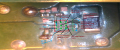
I know that the chip in the first image is dead. I believe it is an IC dedicated to submitting battery level data? Though I am having trouble identifying the IC. Also would like to know where some of these pads go. Not sure if I am seeing some weird shorts or not since I have nothing to compare it to.
1.png
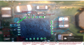
The second image shows where I feel the board warming up with the battery and USB plugged in. Nothing hot just warm and I can't seem to identify what side of the board. With the battery connected and USB I see around a 46mA draw. With the battery removed I see a 36mA draw roughly. I have removed M92t36 chip and the draw is completely gone. Though I do think this chip handles charging along with the dedicated battery controller IC. Still trying to understand the datasheets. Definitely going to look for shorts on pads around M92t36 seat with it removed. Though I think the chip itself is fine maybe.
3.jpg
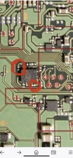
Third picture is a spot I might have accidentally blown a component off highlighted in green. I am not entirely sure if it was just an unpopulated spot or if I blew it off. If anyone knows it would be greatly appreciated.
2.png

I have a few questions about how the Switch turns on circuitry wise. Is the battery really necessary to turn on the switch? Some phones can be turned on with purely USB power. Not sure if the Switch is the same. I have seen a lot of videos show an example plugging in the battery and the USB to test it. If the battery is required is there an IC that checks to see if the battery is in before the power signal is pulled low? Where does the power button signal actually route to? My USB chip might be bad as well but haven't pulled it off this is where I am at currently. I am sure battery power never makes it to M92t36 chip but USB power does. So there is an open between M92t36 and the battery but no clue where the open is or where the battery power routes to.
 
  • Like
Reactions: FXDX

Agilato

Well-Known Member
Member
Joined
Jun 21, 2019
Messages
361
Trophies
0
Age
35
XP
693
Country
United States
I had some faulty switches witch i was able to turn on without battery. But idk, how to reproduce that issue, resistors near BQ chip in battery circuit were missing.
Unfortunately we still don't have schematics for this console to know how is power circuit works...
 
Last edited by Agilato,
  • Like
Reactions: FXDX

Coll6

Member
OP
Newcomer
Joined
Oct 13, 2019
Messages
8
Trophies
0
Age
33
XP
96
Country
United States
I had some faulty switches witch i was able to turn on without battery. But idk, how to reproduce that issue, resistors near BQ chip in battery circuit were missing.
Unfortunately we still don't have schematics for this console to know how is power circuit works...

That is unfortunate but thank you. Any idea where the battery power might feed to on the power side of the board to that chip? Also does seem I might have accidentally blown off a couple of caps by accident. Might you happen to know what values these are? Still getting used to my rework station and that PI3USB30532 was really difficult to remove.crap.png
 

Pintglass

Well-Known Member
Member
Joined
Jan 28, 2019
Messages
364
Trophies
0
Age
52
XP
782
Country
United Kingdom
Looking to repair this Nintendo switch but am a amateur. Wanted to get some ideas and advice from others who might understand how some of this works.
I believe this board is a HAC-CPU-20

What was wrong with your switch before you removed all the ic's and blew components from the board.

Has it been water damaged?
 
  • Like
Reactions: FXDX

Coll6

Member
OP
Newcomer
Joined
Oct 13, 2019
Messages
8
Trophies
0
Age
33
XP
96
Country
United States
What was wrong with your switch before you removed all the ic's and blew components from the board.

Has it been water damaged?
Yeah it was a water damaged Switch I bought off ebay. Trying to learn more about EE and circuit troubleshooting. Can't get it at the college I am going to so learning at my own home workshop. It honestly doesn't look to bad it might be salvageable. The water damage seemed to have avoided the stuff I was worried about the most but until I locate the issue it won't start. I know the battery level circuit was damaged so pulled that off. The USB and Power management chips I think are working fine but there was a little corrosion with them so I pulled them off for now. Isolating the power side from the rest of the board until I can get battery power close to the M92t36 chip which it is not currently. USB power makes it but battery does not. Might indicate the charge circuit might have an issue but wont know until the battery level circuit is repaired. Since I am not exactly sure how this works exactly trying to understand some of the ICs datasheets to get a hint. Going to try to apply a few volts from an outside source to the charger circuit input. If the data sheet is correct it should switch the SYS pin from battery to USB. Though have no clue where the SYS line connects to. At this point just isolating the power side and fixing that first before moving to possible shorts which is why I removed the M92t36 chip. It would be nice to see where some of the power rails for the switch are created from. I know there should be a 5V a 3.3V and a 1.8V(max) rails but no clue what creates them
 

Pintglass

Well-Known Member
Member
Joined
Jan 28, 2019
Messages
364
Trophies
0
Age
52
XP
782
Country
United Kingdom
The main pmic (max77620) on the back side of the board provides the main power rails which needs sys voltage from BQ24193 which comes from the battery or vbus , M92t36 gets power from the pmic 3v3 rail or from vbus.

I'd start by replacing the fuel gauge ic (max17050) and getting sys voltage 4.2 to the pmic.

Also your Battery wont charge with the resistor missing by BQ24193, the one in image 3 of your first post, but you will need to fix fuel gauge first.
 
  • Like
Reactions: Coll6 and FXDX

Pintglass

Well-Known Member
Member
Joined
Jan 28, 2019
Messages
364
Trophies
0
Age
52
XP
782
Country
United Kingdom
Thank you for this ordered some parts but have to becareful about using it. Based on some of the things I have found there are several component level differences on this board compard to the HAC-CPU-01


Yes there is and some of the resistor values in the image @FXDX posted are wrong near BQ24193 so don't follow all of that.
 
Last edited by Pintglass,
  • Like
Reactions: FXDX

Coll6

Member
OP
Newcomer
Joined
Oct 13, 2019
Messages
8
Trophies
0
Age
33
XP
96
Country
United States
The main pmic (max77620) on the back side of the board provides the main power rails which needs sys voltage from BQ24193 which comes from the battery or vbus , M92t36 gets power from the pmic 3v3 rail or from vbus.

I'd start by replacing the fuel gauge ic (max17050) and getting sys voltage 4.2 to the pmic.

Also your Battery wont charge with the resistor missing by BQ24193, the one in image 3 of your first post, but you will need to fix fuel gauge first.

Thanks I wasn't sure about that but thanks for confirming. I will be taking some of the pictures I took and trying to line them up with datasheets. I will submit them here so others can get a better idea how it works.

--------------------- MERGED ---------------------------

Yes there is and some of the resistor values near BQ24193 are wrong as well.
I was afraid of that. Do you know what the right values are?
 

Pintglass

Well-Known Member
Member
Joined
Jan 28, 2019
Messages
364
Trophies
0
Age
52
XP
782
Country
United Kingdom
The resistor your missing next to BQ24193 is 5.6k all the others you can measure, like i said i'd get the fuel gauge sorted first though as your switch won't boot without it.
 

mixelpixx

hardware monkey
Member
Joined
Aug 10, 2014
Messages
133
Trophies
0
Location
y0uR m0mz b0x
XP
356
Country
United States
Remember that resistors and capacitors measure different on the board vs removed from the board (in circuit capacitance and/or resistors in parallel measure less)..

For rework of chips like that I would use hot air, but i would also pre-heat the pcb to 100DegF, will keep ground plane warm while you solder so it doesn't wick away heat.
 
  • Like
Reactions: Agilato and FXDX

Coll6

Member
OP
Newcomer
Joined
Oct 13, 2019
Messages
8
Trophies
0
Age
33
XP
96
Country
United States
The resistor your missing next to BQ24193 is 5.6k all the others you can measure, like i said i'd get the fuel gauge sorted first though as your switch won't boot without it.
Thanks I will order some right now.

Also if anyone cares I got this image of the circuit. It may help someone trying to troubleshoot in this area.
 

Attachments

  • HAC20FuelGauge.png
    HAC20FuelGauge.png
    1.6 MB · Views: 2,034

Coll6

Member
OP
Newcomer
Joined
Oct 13, 2019
Messages
8
Trophies
0
Age
33
XP
96
Country
United States
Here is the BQ24193 Charger IC I am sure that the fuel gauge connects to this maybe through the serial data line but not sure. Will spend time figuring out where they connect but this should give some people an idea how this circuit works and what they should be seeing on each pin. Notice for my BQ24193 it is missing a resistor which is what we are talking about so it could be preventing my battery from outputting due to thermal sense not being setup properly so that's some good news and supports others suggestion. May also explain the fuelgauge being necessary to run the BQ24193
 

Attachments

  • HAC20BQ24193.png
    HAC20BQ24193.png
    2.2 MB · Views: 1,705
  • Like
Reactions: FXDX

Goagerd

Member
Newcomer
Joined
Aug 14, 2022
Messages
8
Trophies
0
Age
50
Location
Berlin
XP
111
Country
Germany
Hi all, does anyone happen to know the ratings of the fuses around the LSM6DSL accelerometer?
 

Attachments

  • IMG_4843.jpg
    IMG_4843.jpg
    2 MB · Views: 225

Site & Scene News

Popular threads in this forum

General chit-chat
Help Users
    K3Nv2 @ K3Nv2: That was scary just had a half a second power flash +1