Hardware GBA Backlight! (AGB-001)

Ozito

Who you gonna call?
Member
Joined
Mar 20, 2006
Messages
411
Trophies
1
Location
Sweden
XP
840
Country
Sweden
Which picture?
I admit I'm confused that no one is able to give me clear answer
Maybe thats specific of this forum

This picture, the yellow dot is next to the "A" on the right side.
It's really really tiny
32g9yOp.jpg


Use a different ground
When you say "different ground" do you mean different source of power for the back light connection?

And if that's not what you meant, what should the yellow dot be connected with?
 

YunGBA

Member
Newcomer
Joined
Jul 12, 2014
Messages
17
Trophies
0
Age
124
XP
55
Country
Poland
This picture, the yellow dot is next to the "A" on the right side.
It's really really tiny
32g9yOp.jpg
YES! Thank you very much, i will try that

My fault i haven't seen last picture, my adblock just blocked it.

So, i see the "new" GND is at point above the "R11" inscrption, but where it should be soldered? To the LCD ribbon i guess?

edit//
I tracked this point, cable can be easily soldered to one of the transistor's pins, here is the picture

dsc00010-jpg.8918

I also tried to connect this "new GND" to a cable that is connected to "P1" on a ribbon, nothing has changed, only screen is not that bright.

Any other solution? I'm uploading another picture with my problem.

DSC00011.jpg
 

Attachments

  • DSC00010.jpg
    DSC00010.jpg
    204.2 KB · Views: 5,476
  • Like
Reactions: Ozito

Ozito

Who you gonna call?
Member
Joined
Mar 20, 2006
Messages
411
Trophies
1
Location
Sweden
XP
840
Country
Sweden
Nothing changed :| thanks for your time tho


Everything looks normal with the old display right?
If so, you should try with a new LCD and try to get some kynar wire instead, try size AWG 28 and while you are at it get some flux to get a nice smooth solder job done.

*EDIT*

Are there any sharp bends on the lcd ribbon? Upload a photo.
 

YunGBA

Member
Newcomer
Joined
Jul 12, 2014
Messages
17
Trophies
0
Age
124
XP
55
Country
Poland
Everything looks normal with the old display right?
If so, you should try with a new LCD and try to get some kynar wire instead, try size AWG 28 and while you are at it get some flux to get a nice smooth solder job done.

*EDIT*

Are there any sharp bends on the lcd ribbon? Upload a photo.

Old display works 100% as new.
I would have to wait another month to get new LCD from china... And spend another cash on it while im not sure it's the LCD issue
Ribbon has been bent, but not too sharp. Paths aren't broken as far as i see. Here is pic

Do you think that LCD could be damaged? They sent me it by normal mail
59wpzo.jpg
 

Dragonhk2005

Member
Newcomer
Joined
Jun 29, 2014
Messages
10
Trophies
0
Age
23
XP
55
Country
Let's try to use LCD creen with original GBA SP backlight mainboard. I don't think LCD damaged because I have a similar problem and I had fixed it by the way above picture. I don't have a diagram of 32 type pinouts but I think you need connect random a some pin to GND, you will see to change of color tone or power turn off. Try again!
 

YunGBA

Member
Newcomer
Joined
Jul 12, 2014
Messages
17
Trophies
0
Age
124
XP
55
Country
Poland
You fixed it by connecting some pin with GND in your GBA, right? How this pin is called? I'll find it in pinout diagram and i will try to connect it.

I don't have access to another LCD, none of my friends use GBA(SP) anymore. Maybe i will buy broken one to check. Does it have to be AGS-101 or it could be 001 as well?

I tried connecting GND with some LCD pins for short period, and some causes high brightness, some low brighness, some makes glitches on the screen, some resets the GBA, some do nothing. I haven't seen this LCD displaying right colors thought.

I was looking at other boards in the web for this or similar problem and i didn't found any. Weird. :|
 

Dragonhk2005

Member
Newcomer
Joined
Jun 29, 2014
Messages
10
Trophies
0
Age
23
XP
55
Country
You fixed it by connecting some pin with GND in your GBA, right? How this pin is called? I'll find it in pinout diagram and i will try to connect it.

I don't have access to another LCD, none of my friends use GBA(SP) anymore. Maybe i will buy broken one to check. Does it have to be AGS-101 or it could be 001 as well?

I tried connecting GND with some LCD pins for short period, and some causes high brightness, some low brighness, some makes glitches on the screen, some resets the GBA, some do nothing. I haven't seen this LCD displaying right colors thought.

I was looking at other boards in the web for this or similar problem and i didn't found any. Weird. :|

My similar problem is occur on the GBA mainboard 40 pins. This label name is P2-VEE but I couldnot found on the mainboard 32 pins. The only way you need to get another SP mainboard to test LCD screen....You do not it but I have a lot of GBA SP...Sad!
 
  • Like
Reactions: YunGBA

YunGBA

Member
Newcomer
Joined
Jul 12, 2014
Messages
17
Trophies
0
Age
124
XP
55
Country
Poland
Guys, I FIXED IT!!!

I connected pins: COM + REVC + GND
AND IT WORKED! I'm very happy. My girlfriend didn't believe i will make it ;D

Thank you all for your help! You tracked me to trial and error with GND!
n6yphi.jpg
 

Dragonhk2005

Member
Newcomer
Joined
Jun 29, 2014
Messages
10
Trophies
0
Age
23
XP
55
Country
Guys, I FIXED IT!!!

I connected pins: COM + REVC + GND
AND IT WORKED! I'm very happy. My girlfriend didn't believe i will make it ;D

Thank you all for your help! You tracked me to trial and error with GND!
n6yphi.jpg

A nice shot!!!

I throught you didnot believe me :)
 

HungLo

New Member
Newbie
Joined
May 2, 2006
Messages
2
Trophies
0
XP
182
Country
United States
A nice shot!!!

I throught you didnot believe me :)

YunGBA and Dragonhk2005 - thank you both so much!

I installed an AGS-101 screen in my 32-pin GBA but the screen had streaks, was washed out and adjusting the pot did not help. Searching for answers led me to this thread.

Although my screen problem was not as severe as YunGBA, the solution of soldering a wire between points REVC and GND instantly fixed my problem. Now when adjusting the pot, I get a proper blend of brightness and color saturation.

Thank you both for sharing your knowledge and experience as it helped resolve my problem and will surely help others!
 

YunGBA

Member
Newcomer
Joined
Jul 12, 2014
Messages
17
Trophies
0
Age
124
XP
55
Country
Poland
YunGBA and Dragonhk2005 - thank you both so much!

I installed an AGS-101 screen in my 32-pin GBA but the screen had streaks, was washed out and adjusting the pot did not help. Searching for answers led me to this thread.

Although my screen problem was not as severe as YunGBA, the solution of soldering a wire between points REVC and GND instantly fixed my problem. Now when adjusting the pot, I get a proper blend of brightness and color saturation.

Thank you both for sharing your knowledge and experience as it helped resolve my problem and will surely help others!

Wow, im happy im not the only one who resolved this problem.
I think that connecting the GND disables the pot (im not sure about it), and you still can use it because you only connected REVC and COM.
I will check it and post result, for now im not disassembling my GBA because im using it all the time since i got the LCD working.
Happy night-playing!
 

HungLo

New Member
Newbie
Joined
May 2, 2006
Messages
2
Trophies
0
XP
182
Country
United States
Wow, im happy im not the only one who resolved this problem.
I think that connecting the GND disables the pot (im not sure about it), and you still can use it because you only connected REVC and COM.
I will check it and post result, for now im not disassembling my GBA because im using it all the time since i got the LCD working.
Happy night-playing!


No need to disassemble as the pot works fine with REVC and GND connected. I did not connect COM to REVC as everything seems to work OK.

Prior to connecting REVC to GND, adjusting the pot resulted in a washed out screen with streaks. Only the brightness seemed to change when turning the pot. After connecting REVC to GND, adjusting the pot results in nice color saturation and display brightness without streaks. Basically, the pot now functions completely normal and the screen performance matches my GBA SP with AGS-101.

I left the system on for a couple of hours running on rechargeable Sanyo Eneloop batteries and everything is working fine:)
 
  • Like
Reactions: Dragonhk2005

MastahXd

Member
Newcomer
Joined
Jul 14, 2014
Messages
11
Trophies
0
Age
37
XP
55
Country
Poland
As this is my first post on this forum, I'd like to say hello to everyone.
20140714_220453.jpg
Using some of the information from this thread I recently completed the installation of mine backlit screen I ordered from Aliexpress
20140713_095423.jpg

As you all can see my workspace is on a kitchen counter, but still i managed to complete my goal. I installed the AGS-101 screen without the ribbon cable kit and here is how i did it. First of all I wouldn't have done that without a great makro from my phone using a simple piece of equipment i made recently :-)
20140710_233904.jpg

20140710_233908.jpg

I used the ribbon cable from my original no backlight screen and set it where it supposed to be, then I scored the lines to mark the position.
20140710_225011.jpg

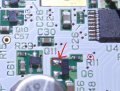
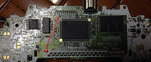
Then I scrubbed some of the capton tape from the ribbon with a scalpel and soldered the coil wires to it, all 32 of them to be exact. I also checked them for any shorts using my makro lens :-)
20140711_180015.jpg
20140711_181304.jpg
20140711_000249.jpg
20140711_190743.jpg

20140711_191329.jpg

After that i needed to trace all the test pins onto the original ribbon in order to know how to connect it to the screen's ribbon, because I couldn't find the pinout for the 32 pins mainboard anywhere. It turns out that pins 1-32 match exactly AGS-101's pinout. Pins 32 and 33 on screens ribbon are soldered to pin 32(GND) on the mainboard's side and pin 34 is soldered to the transistor leg on the mainboard (33 and 34 are the backlight pins) Here are some pictures my completed work and some first tests (the screen reqired pot adjustment, because the picture faded away after a few seconds)
20140713_115247.jpg

Thanks to my makro lens I've found three shorts which i cut with a scalpel, in order not to desolder the wires. Thanks to that it worked on the very first try "yay" :-)
20140713_115522.jpg

20140713_121038.jpg

Faded picture:
20140713_121041.jpg
20140713_121046.jpg

After making sure everything works correctly, I started to assemble the console. The original ribbon, as well as the screens ribbon, are sticked to the back of the screen with double sided tape only without any other isolation. On top of that I used the padding from the original screen.
20140713_123629.jpg

20140713_124956.jpg

The end effect are beautiful saturated colors and great visibility of what is going on in the games. I'm quite proud of my work so i decided to spend last 40 minutes of my life sharing it with you. I hope that you'll appreciate it and that this post will be useful to some of the people like me, who don't want to spent 15-20 USD or don't have access to the ribbon kits ;-P. (I also took this effort to keep the mainboard as intact as possible)
 

Site & Scene News

Popular threads in this forum

General chit-chat
Help Users
    AncientBoi @ AncientBoi: byes