This is just another saying for dont do the mod.For safety reason, take everything out before running the ofw.

This is just another saying for dont do the mod.For safety reason, take everything out before running the ofw.
You might be exactly right.Yes, lite is safe.
I silently read, people whose got blackscreen (corupted data) usually oled. My hunch says that Dat0 adapter is the main cause.
People might assume if the pico take out, cut off the whole cable, and take pico out, then its save to boot into ofw, it doesn't. You need to take out the Dat0 adapter (and the mosfet). Because if its Short circuited the dat0 and dat1, when the OS running, it will corrupt the whole data.
For safety reason, take everything out before running the ofw.
I mean, if you do the mod, don't go to OFW until the mod is working.This is just another saying for dont do the mod.
Yup, ill remember this just for caution, esspecially with oled and luckily i havent had any oled yet. Still not convince enough with that adapter instalation.I mean, if you do the mod, don't go to OFW until the mod is working.
If you want to go to the OFW while the mod is unsuccessfull, then the save one is to reverse everything you modded, then run the OFW.
Go to OFW, while the mod is unsuccessfull is risky. The OS might broke something because of the fault mod.
Lite is the most easy, its around the Dat0 pad.Is there a pad or via connected with dat1 on the PCB?
If you are trying to test the diode values of a connection that is shorting dat0 to dat1, the easiest way to do this would be on a v1 switch. I could probably test it on mine. I imagine the same values would carry over to any other switch iteration since its all the same emmc chips.Is there a pad or via connected with dat1 on the PCB?
Not sure about the same values, but there are different brand of emmc chips.If you are trying to test the diode values of a connection that is shorting dat0 to dat1, the easiest way to do this would be on a v1 switch. I could probably test it on mine. I imagine the same values would carry over to any other switch iteration since its all the same emmc chips.
The backside, you need to take the board out and flipped it.Can anyone tell me which side of the board SDA and SCL are in the switch lite?
I realized that right after I posted.The backside, you need to take the board out and flipped it.
 looked at a donor board. Thank you.
Check your MOSFETs.I realized that right after I posted.
Post automatically merged:
Post automatically merged:
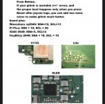
I’m getting this error. Lights are yellow. Normally I’m able to fix this with the SDA and SCL wires but it’s not working this time. This is on a switch lite.
Yes i agree.Check your MOSFETs.
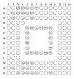
@abal1000x I've read everything you said about dat0 adaptor, Someone once shared the pinout of the eMMC and claimed that shifting the dat0 adaptor as far left as possible is the safest bet. Since the point left to dat0 is empty. Do you agree?
This already tested and works? how many times now?Yes i agree.
That is me, the one who suggesting to shifting to left (to right if in front view).
What model RP oled? Just installed 4 of them yesterday and some more the day before and all working satis. What adaptor are you using and how are you attaching it?Post automatically merged:
This board has a record of damaging EMMC in my locality
Please check for faults at PIN15I realized that right after I posted.
Post automatically merged:
Post automatically merged:
I’m getting this error. Lights are yellow. Normally I’m able to fix this with the SDA and SCL wires but it’s not working this time. This is on a switch lite.
Its still experimentation. Only once.This already tested and works? how many times now?
Error: ==* CPU always reach BCT check (no glitch reaction, check mosfet)I realized that right after I posted.
Post automatically merged:
Post automatically merged:
I’m getting this error. Lights are yellow. Normally I’m able to fix this with the SDA and SCL wires but it’s not working this time. This is on a switch lite.
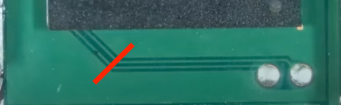
Ops. Sorry. Thanks. Will make sure to always do that. What about cutting the traces of the two pads? Would you do it?Yes i agree.
That is me, the one who suggesting to shifting to left (to right if in front view).
Why cut them?Ops. Sorry. Thanks. Will make sure to always do that. What about cutting the traces of the two pads? Would you do it?