I've personally never done it exactly like that but I have cut the whole CPU part of the shield off in the past and mounted the heat pipe directly on the dye. You have to be careful though because doing the way I did there is a chance you can crack the dye or get uneven mount and personally I noticed no temperature difference so I would just do it with the copper sticker intact. That's just my input though.i saw some people remove the copper tape.
removing the copper good or bad idea??
View attachment 375902
You are using an out of date browser. It may not display this or other websites correctly.
You should upgrade or use an alternative browser.
You should upgrade or use an alternative browser.
Staff Posts
Recent threadmarks
sharing files
Important Posts
Recent threadmarks
Firmwares
You try remove (desolder) cpu point 15 wier on pico and try tearn on console.Update
I change my dat0 adapter because it suck and my emmc error
And now i got succes led
But now screen just blank
I cannot get into hekate
So how can i repair my boot0?
See the lcd Flex me be it is disconect or some thing of lce not conect. Or sd card exfat not have hekate files remove it . It also can get black secreen.
Last edited by Danook28,

Without pico is the sameYou try remove cpu point 15 wier on pico and try tearn on console.
Blank screen
After that instal pico and new dat0 adapter
Got succes led but
Just blank screen to
- Joined
- Jul 12, 2010
- Messages
- 162
- Trophies
- 1
- Age
- 36
- Location
- Bananna Land.
- Website
- www.nerdfy.com.br
- XP
- 835
- Country

i got 0,85 v read in both capacitors when button power is pressed.1.0 uf 6.3 v ( 0201)
yes, i wanted to know how the temperature difference.I've personally never done it exactly like that but I have cut the whole CPU part of the shield off in the past and mounted the heat pipe directly on the dye. You have to be careful though because doing the way I did there is a chance you can crack the dye or get uneven mount and personally I noticed no temperature difference so I would just do it with the copper sticker intact. That's just my input though.
but im gonna stick with the default without tear the copper sticker.
Does it get to the "NO SD" screen if you remove the SD card daughter board? Unplug battery and remove that board then replug battery and tryWithout pico is the same
Blank screen
After that instal pico and new dat0 adapter
Got succes led but
Just blank screen to
See also cmd point resistor me be short.if nothing bad on soldring point that meaning your dat0 adapter under chip bridge to dat1. You must read dat0 value before you mode console brother it is so risky.Without pico is the same
Blank screen
After that instal pico and new dat0 adapter
Got succes led but
Just blank screen to
Post automatically merged:
Brother must use microscope to see from where the smook is happend and why.coz you cant desolder this 2 capacitor if it still fine. It is risky if you dont know how you solder desoler capacitor very small mate.i got 0,85 v read in both capacitors when button power is pressed.
Last edited by Danook28,
still blank screenDoes it get to the "NO SD" screen if you remove the SD card daughter board? Unplug battery and remove that board then replug battery and try
i think my first dat0 adapter make dat0 bridge to dat1See also cmd point resistor me be short.if nothing bad on soldring point that meaning your dat0 adapter under chip bridge to dat1. You must read dat0 value before you mode console brother it is so risky.
thats why i got error and cannot get into ofw
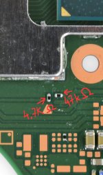
so add another resistor 47+47, and blank screen came
i remove pico still same
and now i change dat0 adapter and cut a little to make sure dat0 and dat1 dont bridge
dat0 value 650
led succes but blank
btw can switch with broken emmc access hekate menu?

The thing is that if those caps are shorted/damaged the switch won't boot, but if you remove them altogether the switch works.i got 0,85 v read in both capacitors when button power is pressed.
The easiest way is to inspect them visualy (they change color and/or explode) and do a diode test (check if you get a continuous beep)
Anyway, that might not be your problem.
Check also the resistors on CMD point (photo)
Attachments

1uf 6.3vCan someone please tell me what is the 3.3v point capacitor value on the v2?
I want to see pic of hekate menu or error. You can see emmc nand info or creat emummc????still blank screen
i think my first dat0 adapter make dat0 bridge to dat1
thats why i got error and cannot get into ofw
so add another resistor 47+47, and blank screen came
i remove pico still same
and now i change dat0 adapter and cut a little to make sure dat0 and dat1 dont bridge
dat0 value 650
led succes but blank
btw can switch with broken emmc access hekate menu?
If 3v3 capacitor near charge ic chip it is 1uf 6.3V 0402Can someone please tell me what is the 3.3v point capacitor value on the v2?
Always use leaded solder, it makes life easier.One question for experienced users.
Should we use lead based tin or lead free tin? I read that lead based melts at lower temperatures.
Any advices in which tin should I use?
The best one in my experience is sn62pb36ag2 or sn63pb37.
Edit: if you are soldering as full time job, you might consider lead free (and other safety measures) since the fumes are not as toxic but otherwise using lead based should not be a problem, we inhale much more toxic crap from our surroundings every day.
Last edited by QuiTim,
i cannot get into hekateI want to see pic of hekate menu or error. You can see emmc nand info or creat emummc????
just blank screen

Hello everyone, there is a light switch with an emmc blade, the stock does not start, the purple screen, the atmosphere does not start, I get an error Failed to initialize eMMC, Failed to start HOS
hekate gives an error failed to init emmc please tell me if there is an option to build emunand and run it with a dead emmc ?
hekate gives an error failed to init emmc please tell me if there is an option to build emunand and run it with a dead emmc ?
- Joined
- Jul 12, 2010
- Messages
- 162
- Trophies
- 1
- Age
- 36
- Location
- Bananna Land.
- Website
- www.nerdfy.com.br
- XP
- 835
- Country
I checked the cmd point, and got the results below in the legend. Remembering that I put the red probe (+) on the components and the black probe (-) grounded on the metal that covers the usb. diode test.The thing is that if those caps are shorted/damaged the switch won't boot, but if you remove them altogether the switch works.
The easiest way is to inspect them visualy (they change color and/or explode) and do a diode test (check if you get a continuous beep)
Anyway, that might not be your problem.
Check also the resistors on CMD point (photo)
Is it hope?
")

你在這裡用的是哪個mosfet?
Chack SD CARD Cluster 128 ~ 512 kibthe files on the sd are the same that work fine on the v2, lite and oled that i have made. Does v1 have something different?
Post automatically merged:
the error i get when i start cfw
Picoflu fw :2.6x ?
I think you need to replace the "no beep" one.I checked the cmd point, and got the results below in the legend. Remembering that I put the red probe (+) on the components and the black probe (-) grounded on the metal that covers the usb. diode test.
Is it hope?
View attachment 375912
Can you measure it in Ohm mode to see what value it gives?
what's the reading in the diode mode on both sides of CMD resistor?I checked the cmd point, and got the results below in the legend. Remembering that I put the red probe (+) on the components and the black probe (-) grounded on the metal that covers the usb. diode test.
Is it hope?
Similar threads
- Replies
- 3
- Views
- 755
- Replies
- 42
- Views
- 5K
- Replies
- 5
- Views
- 1K
- Replies
- 6
- Views
- 2K
- Replies
- 8
- Views
- 2K
Site & Scene News
New Hot Discussed
-
-
58K views
Nintendo Switch firmware 18.0.0 has been released
It's the first Nintendo Switch firmware update of 2024. Made available as of today is system software version 18.0.0, marking a new milestone. According to the patch... -
29K views
GitLab has taken down the Suyu Nintendo Switch emulator
Emulator takedowns continue. Not long after its first release, Suyu emulator has been removed from GitLab via a DMCA takedown. Suyu was a Nintendo Switch emulator... -
21K views
Atmosphere CFW for Switch updated to pre-release version 1.7.0, adds support for firmware 18.0.0
After a couple days of Nintendo releasing their 18.0.0 firmware update, @SciresM releases a brand new update to his Atmosphere NX custom firmware for the Nintendo...by ShadowOne333 94 -
18K views
Wii U and 3DS online services shutting down today, but Pretendo is here to save the day
Today, April 8th, 2024, at 4PM PT, marks the day in which Nintendo permanently ends support for both the 3DS and the Wii U online services, which include co-op play...by ShadowOne333 176 -
15K views
GBAtemp Exclusive Introducing tempBOT AI - your new virtual GBAtemp companion and aide (April Fools)
Hello, GBAtemp members! After a prolonged absence, I am delighted to announce my return and upgraded form to you today... Introducing tempBOT AI 🤖 As the embodiment... -
12K views
Pokemon fangame hosting website "Relic Castle" taken down by The Pokemon Company
Yet another casualty goes down in the never-ending battle of copyright enforcement, and this time, it hit a big website which was the host for many fangames based and...by ShadowOne333 65 -
11K views
MisterFPGA has been updated to include an official release for its Nintendo 64 core
The highly popular and accurate FPGA hardware, MisterFGPA, has received today a brand new update with a long-awaited feature, or rather, a new core for hardcore...by ShadowOne333 51 -
11K views
Apple is being sued for antitrust violations by the Department of Justice of the US
The 2nd biggest technology company in the world, Apple, is being sued by none other than the Department of Justice of the United States, filed for antitrust...by ShadowOne333 80 -
10K views
The first retro emulator hits Apple's App Store, but you should probably avoid it
With Apple having recently updated their guidelines for the App Store, iOS users have been left to speculate on specific wording and whether retro emulators as we... -
9K views
"TMNT: The Hyperstone Heist" for the SEGA Genesis / Mega Drive gets a brand new DX romhack with new features
The romhacking community is always a source for new ways to play retro games, from completely new levels or stages, characters, quality of life improvements, to flat...by ShadowOne333 36
-
-
-
223 replies
Nintendo Switch firmware 18.0.0 has been released
It's the first Nintendo Switch firmware update of 2024. Made available as of today is system software version 18.0.0, marking a new milestone. According to the patch...by Chary -
176 replies
Wii U and 3DS online services shutting down today, but Pretendo is here to save the day
Today, April 8th, 2024, at 4PM PT, marks the day in which Nintendo permanently ends support for both the 3DS and the Wii U online services, which include co-op play...by ShadowOne333 -
169 replies
GBAtemp Exclusive Introducing tempBOT AI - your new virtual GBAtemp companion and aide (April Fools)
Hello, GBAtemp members! After a prolonged absence, I am delighted to announce my return and upgraded form to you today... Introducing tempBOT AI 🤖 As the embodiment...by tempBOT -
146 replies
GitLab has taken down the Suyu Nintendo Switch emulator
Emulator takedowns continue. Not long after its first release, Suyu emulator has been removed from GitLab via a DMCA takedown. Suyu was a Nintendo Switch emulator...by Chary -
96 replies
The first retro emulator hits Apple's App Store, but you should probably avoid it
With Apple having recently updated their guidelines for the App Store, iOS users have been left to speculate on specific wording and whether retro emulators as we...by Scarlet -
94 replies
Atmosphere CFW for Switch updated to pre-release version 1.7.0, adds support for firmware 18.0.0
After a couple days of Nintendo releasing their 18.0.0 firmware update, @SciresM releases a brand new update to his Atmosphere NX custom firmware for the Nintendo...by ShadowOne333 -
80 replies
Apple is being sued for antitrust violations by the Department of Justice of the US
The 2nd biggest technology company in the world, Apple, is being sued by none other than the Department of Justice of the United States, filed for antitrust...by ShadowOne333 -
74 replies
Delta emulator now available on the App Store for iOS
The time has finally come, and after many, many years (if not decades) of Apple users having to side load emulator apps into their iOS devices through unofficial...by ShadowOne333 -
65 replies
Pokemon fangame hosting website "Relic Castle" taken down by The Pokemon Company
Yet another casualty goes down in the never-ending battle of copyright enforcement, and this time, it hit a big website which was the host for many fangames based and...by ShadowOne333 -
53 replies
Nintendo "Indie World" stream announced for April 17th, 2024
Nintendo has recently announced through their social media accounts that a new Indie World stream will be airing tomorrow, scheduled for April 17th, 2024 at 7 a.m. PT...by ShadowOne333
-
Popular threads in this forum
General chit-chat
-
 Xdqwerty
Loading…what are you looking at?
Xdqwerty
Loading…what are you looking at?
-
-
-
-
-
-
-
-
-
-
-
-
-
-
-
 @
RedColoredStars:
There is an actual trailer with footage too. lol. Going to watch it tonight. Grabbed it from... a place.
@
RedColoredStars:
There is an actual trailer with footage too. lol. Going to watch it tonight. Grabbed it from... a place. -
-
 @
SylverReZ:
@Psionic Roshambo, JonTron's back yet again until he disappears into the void for another 6 or so months.+1
@
SylverReZ:
@Psionic Roshambo, JonTron's back yet again until he disappears into the void for another 6 or so months.+1 -
-
-
-
-
-
-
-