


Buy new mmc chip and restore full nand backup to it .. It is working brother.With the chip placed, the console does not start in original mode, if I remove it, it does start original, I already changed the micro sd card for another and the same result
You are using an out of date browser. It may not display this or other websites correctly.
You should upgrade or use an alternative browser.
You should upgrade or use an alternative browser.
Staff Posts
Recent threadmarks
sharing files
Important Posts
Recent threadmarks
Firmwares
I've done 8+ MOSFETs installations on all models, never used a resistor. Glitches in seconds.I am also a fan of green led for success. Looking green led make me feel relief that nothing wrong. It would be great if you get it back in next version. This is my silly idea but BGR and RGB only revert led B and R right. so green should be the same for both, Am I right. It still make me wonder since G and R be revert instead off B and R like the name it should.
I guess I will stick with lower fw version in the meantime. btw, Is that necessary to put resistor to the mosfet. I found it exist on the cable, but it seem some people put it in mosfet and soneone doent. And what is that purpose of it

With the chip placed, the console does not start in original mode, if I remove it, it does start original, I already changed the micro sd card for another and the same result
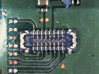
I think you need double resistors on dat0 and cmd. I had the same problem on one of my v1's, double resistors fixed it.

Could you provide a diagram of how to place the resistors?I think you need double resistors on dat0 and cmd. I had the same problem on one of my v1's, double resistors fixed it.
Could you provide a diagram of how to place the resistors?
Attachments
man you're great... Console working on ofw and cfw adding a second resistor at points 28 and 29 thank you very much!!!
Post automatically merged:
Could you provide a diagram of how to place the resistors?
man you're great... Console working on ofw and cfw adding a second resistor at points 28 and 29 thank you very much!!!I think you need double resistors on dat0 and cmd. I had the same problem on one of my v1's, double resistors fixed it.
Nice!man you're great... Console working on ofw and cfw adding a second resistor at points 28 and 29 thank you very much!!!
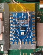
Everyone, I think it's time we update the resistor recommendations. I've tested double 47ohm on an oled, a lite and a bunch of v1's and they all work fine, and most of the v1's didn't without. Haven't seen any situation where it causes problems. @rehius @lightninjay @Adran_Marit
I have no issue with updating to default installations including 94 ohm on Dat0 and CMD pads of the RP2040. I also need to update and include ALL of the LED codes now that it seems we've stabilized into an area of comprehensiveness. I think the main reason we have left it ambiguous is because we have not made a wire size/thickness requirement, and different resistances of wire diameter could have some effect potentially.Nice!
Everyone, I think it's time we update the resistor recommendations. I've tested double 47ohm on an oled, a lite and a bunch of v1's and they all work fine, and most of the v1's didn't without. Haven't seen any situation where it causes problems. @rehius @lightninjay @Adran_Marit

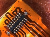
here pics, 2nd pics first boton pad broken 1 leg but i supose y can touch the other flex pads (pic 3)Add pic for help.
Attachments
Is it fine to use 0.1 mm magnet wier to mosfet sp1 sp2 capacitor and pico point on motherbord.
Post automatically merged:
I dont think if is need more skill use magnate copper wier to that broken leg to soldring it from out side or flat copper pads that use for fix rip pads . Or replace it part. If it not conect to gother.here pics, 2nd pics first boton pad broken 1 leg but i supose y can touch the other flex pads (pic 3)
Last edited by Danook28,
- Joined
- Jul 12, 2010
- Messages
- 162
- Trophies
- 1
- Age
- 36
- Location
- Bananna Land.
- Website
- www.nerdfy.com.br
- XP
- 835
- Country

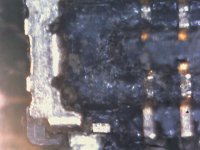
So Goodfellas, my time has come, it's tradition every generation for me to take a big financial loss, I think I burned my Nintendo Switch OLED.
I still have no idea what caused it, but I believe it was my mosfet mount that shorted out to the metal casing that covers the CPU. When I turned it on, there was smoke somewhere. It is currently in BSOD (Black).
Does anyone have any tips for me to try to check if there is salvation? Maybe a blown fuse, or a blown component. (I know it might just be empty hope).
I wanted to check out the mainboard, before thinking about the possibilities, I'm already looking at mainboards to buy...

You should trace what component burn, that is your best clue.So Goodfellas, my time has come, it's tradition every generation for me to take a big financial loss, I think I burned my Nintendo Switch OLED.
I still have no idea what caused it, but I believe it was my mosfet mount that shorted out to the metal casing that covers the CPU. When I turned it on, there was smoke somewhere. It is currently in BSOD (Black).
Does anyone have any tips for me to try to check if there is salvation? Maybe a blown fuse, or a blown component. (I know it might just be empty hope).
I wanted to check out the mainboard, before thinking about the possibilities, I'm already looking at mainboards to buy...
Using microscope find some 'explosion' matter splatter around.

You can always buy a new one but it's more fun to try and fix it.So Goodfellas, my time has come, it's tradition every generation for me to take a big financial loss, I think I burned my Nintendo Switch OLED.
I still have no idea what caused it, but I believe it was my mosfet mount that shorted out to the metal casing that covers the CPU. When I turned it on, there was smoke somewhere. It is currently in BSOD (Black).
Does anyone have any tips for me to try to check if there is salvation? Maybe a blown fuse, or a blown component. (I know it might just be empty hope).
I wanted to check out the mainboard, before thinking about the possibilities, I'm already looking at mainboards to buy...
Some pictures and background story would provide a good starting point for some people here to try to help you.
In any case, first I would check the voltage draw then see where that takes you.
So Goodfellas, my time has come, it's tradition every generation for me to take a big financial loss, I think I burned my Nintendo Switch OLED.
I still have no idea what caused it, but I believe it was my mosfet mount that shorted out to the metal casing that covers the CPU. When I turned it on, there was smoke somewhere. It is currently in BSOD (Black).
Does anyone have any tips for me to try to check if there is salvation? Maybe a blown fuse, or a blown component. (I know it might just be empty hope).
I wanted to check out the mainboard, before thinking about the possibilities, I'm already looking at mainboards to buy...
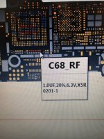
Sp1 sp2 capacitor read in multimater this is the capacitor first read.


Because it's the bare dye it's pretty important to cover it completely so I personally just put a big blob on there large enough that I know for sure it will squeeze out and cover the entire surface of the dye when I put the shield and heat pipe back on. You protected your CPU points so don't be afraid to use "too much" paste.any tips or method
how much i need to put/apply the thermal pasta??
View attachment 375900
so it doesnt overheat etc
thx

- Joined
- Jul 12, 2010
- Messages
- 162
- Trophies
- 1
- Age
- 36
- Location
- Bananna Land.
- Website
- www.nerdfy.com.br
- XP
- 835
- Country
I've already started doing it. I removed all the rp2040 cables from the board, and tested the 3.3v point, reads 3.35v when power button was pressed. currently no component in the heatsink fan region seems burnt, the smoke in my view came from that region.You should trace what component burn, that is your best clue.
Using microscope find some 'explosion' matter splatter around.
It's always nice to fix, I confess I'm inclined to really try. I'm checking the voltages, when the power button is pressed the 3.3v point where the picofly's power wire is installed reads 3.35v. Then energy arrives in that region.You can always buy a new one but it's more fun to try and fix it.
Some pictures and background story would provide a good starting point for some people here to try to help you.
In any case, first I would check the voltage draw then see where that takes you.
What are the reference values?Sp1 sp2 capacitor read in multimater this is the capacitor first read.
i saw some people remove the copper tape.Because it's the bare dye it's pretty important to cover it completely so I personally just put a big blob on there large enough that I know for sure it will squeeze out and cover the entire surface of the dye when I put the shield and heat pipe back on. You protected your CPU points so don't be afraid to use "too much" paste.
removing the copper good or bad idea??
1.0 uf 6.3 v ( 0201)I've already started doing it. I removed all the rp2040 cables from the board, and tested the 3.3v point, reads 3.35v when power button was pressed. currently no component in the heatsink fan region seems burnt, the smoke in my view came from that region.
It's always nice to fix, I confess I'm inclined to really try. I'm checking the voltages, when the power button is pressed the 3.3v point where the picofly's power wire is installed reads 3.35v. Then energy arrives in that region.
What are the reference values?
Attachments
Last edited by Danook28,
UpdateHello, i bought new switch oled and get toshiba nand
when i press the power on
Picofly logo show normaly, when i press volume -+ to get OFW, just show blackscreen
I unplug battery and plug in back, i got error ** (RST)
I change RST cable and now got =**
Picofly logo show again and cannot get into OFW
Just blakscreen again
So i add more resistor cause i think toshiba need more resistor (47+47)
And now got =***
I change my dat0 adapter because it suck and my emmc error
And now i got succes led
But now screen just blank
I cannot get into hekate
So how can i repair my boot0?
Attachments
Similar threads
- Replies
- 3
- Views
- 842
- Replies
- 42
- Views
- 5K
- Replies
- 5
- Views
- 1K
- Replies
- 6
- Views
- 2K
- Replies
- 8
- Views
- 2K
Site & Scene News
New Hot Discussed
-
-
61K views
Nintendo Switch firmware 18.0.0 has been released
It's the first Nintendo Switch firmware update of 2024. Made available as of today is system software version 18.0.0, marking a new milestone. According to the patch... -
22K views
Atmosphere CFW for Switch updated to pre-release version 1.7.0, adds support for firmware 18.0.0
After a couple days of Nintendo releasing their 18.0.0 firmware update, @SciresM releases a brand new update to his Atmosphere NX custom firmware for the Nintendo...by ShadowOne333 94 -
20K views
Wii U and 3DS online services shutting down today, but Pretendo is here to save the day
Today, April 8th, 2024, at 4PM PT, marks the day in which Nintendo permanently ends support for both the 3DS and the Wii U online services, which include co-op play...by ShadowOne333 179 -
16K views
GBAtemp Exclusive Introducing tempBOT AI - your new virtual GBAtemp companion and aide (April Fools)
Hello, GBAtemp members! After a prolonged absence, I am delighted to announce my return and upgraded form to you today... Introducing tempBOT AI 🤖 As the embodiment... -
12K views
Pokemon fangame hosting website "Relic Castle" taken down by The Pokemon Company
Yet another casualty goes down in the never-ending battle of copyright enforcement, and this time, it hit a big website which was the host for many fangames based and...by ShadowOne333 65 -
12K views
The first retro emulator hits Apple's App Store, but you should probably avoid it
With Apple having recently updated their guidelines for the App Store, iOS users have been left to speculate on specific wording and whether retro emulators as we... -
12K views
MisterFPGA has been updated to include an official release for its Nintendo 64 core
The highly popular and accurate FPGA hardware, MisterFGPA, has received today a brand new update with a long-awaited feature, or rather, a new core for hardcore...by ShadowOne333 51 -
11K views
Delta emulator now available on the App Store for iOS
The time has finally come, and after many, many years (if not decades) of Apple users having to side load emulator apps into their iOS devices through unofficial...by ShadowOne333 95 -
10K views
"TMNT: The Hyperstone Heist" for the SEGA Genesis / Mega Drive gets a brand new DX romhack with new features
The romhacking community is always a source for new ways to play retro games, from completely new levels or stages, characters, quality of life improvements, to flat...by ShadowOne333 36 -
9K views
Anbernic announces RG35XX 2024 Edition retro handheld
Retro handheld manufacturer Anbernic is releasing a refreshed model of its RG35XX handheld line. This new model, named RG35XX 2024 Edition, features the same...
-
-
-
225 replies
Nintendo Switch firmware 18.0.0 has been released
It's the first Nintendo Switch firmware update of 2024. Made available as of today is system software version 18.0.0, marking a new milestone. According to the patch...by Chary -
179 replies
Wii U and 3DS online services shutting down today, but Pretendo is here to save the day
Today, April 8th, 2024, at 4PM PT, marks the day in which Nintendo permanently ends support for both the 3DS and the Wii U online services, which include co-op play...by ShadowOne333 -
169 replies
GBAtemp Exclusive Introducing tempBOT AI - your new virtual GBAtemp companion and aide (April Fools)
Hello, GBAtemp members! After a prolonged absence, I am delighted to announce my return and upgraded form to you today... Introducing tempBOT AI 🤖 As the embodiment...by tempBOT -
96 replies
The first retro emulator hits Apple's App Store, but you should probably avoid it
With Apple having recently updated their guidelines for the App Store, iOS users have been left to speculate on specific wording and whether retro emulators as we...by Scarlet -
95 replies
Delta emulator now available on the App Store for iOS
The time has finally come, and after many, many years (if not decades) of Apple users having to side load emulator apps into their iOS devices through unofficial...by ShadowOne333 -
94 replies
Atmosphere CFW for Switch updated to pre-release version 1.7.0, adds support for firmware 18.0.0
After a couple days of Nintendo releasing their 18.0.0 firmware update, @SciresM releases a brand new update to his Atmosphere NX custom firmware for the Nintendo...by ShadowOne333 -
65 replies
Pokemon fangame hosting website "Relic Castle" taken down by The Pokemon Company
Yet another casualty goes down in the never-ending battle of copyright enforcement, and this time, it hit a big website which was the host for many fangames based and...by ShadowOne333 -
53 replies
Nintendo "Indie World" stream announced for April 17th, 2024
Nintendo has recently announced through their social media accounts that a new Indie World stream will be airing tomorrow, scheduled for April 17th, 2024 at 7 a.m. PT...by ShadowOne333 -
51 replies
MisterFPGA has been updated to include an official release for its Nintendo 64 core
The highly popular and accurate FPGA hardware, MisterFGPA, has received today a brand new update with a long-awaited feature, or rather, a new core for hardcore...by ShadowOne333 -
43 replies
Nintendo Switch firmware update 18.0.1 has been released
A new Nintendo Switch firmware update is here. System software version 18.0.1 has been released. This update offers the typical stability features as all other...by Chary
-
