Hacking Hardware Picofly - a HWFLY switch modchip

Takezo-San

Well-Known Member
Member
Joined
May 3, 2023
Messages
261
Trophies
0
Age
39
XP
348
Country
Seychelles
Hello here I am with a Oled that has the same Problem after a hwfly install (no I did not install the hwfly) someone else did , so this has nothing to do with the picofly this is a issue that occurs during installation
User install error. Very likely too. Another variable to take into account.

Edit - Thinking about this more it could also have been a bad/defect hwfly chip or defect apu flex cable, @LogicalMadness can tell you all about that. Just too many user based + unknown variables to pin point errors and too highlight them to avoid in future installs.
 
Last edited by Takezo-San,
  • Like
Reactions: QuiTim

abal1000x

Well-Known Member
Member
Joined
Jun 5, 2022
Messages
1,059
Trophies
0
XP
1,353
Country
Gaza Strip

Dee87

Well-Known Member
Member
Joined
Mar 19, 2023
Messages
1,139
Trophies
1
XP
1,574
Country
Germany
User install error. Very likely too. Another variable to take into account.
i Would account that as the only error.

i installed over 25 picoflys now in all switches with emmc types and i never had an issue.

so i can confirm the pico works on every variable of the hardware that are available if its installed correct
 

Nephiel

Artificer
Member
Joined
Nov 3, 2002
Messages
267
Trophies
2
XP
809
Country
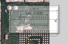
View attachment 375412
This is what in my mind, which i thought its more secured.

Also the left and right part might be extended like usual to secured it even more.
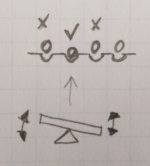
With more than 1-2 points, if any solder protrudes ever-so-slightly *more* than the others, neighboring points will fail. If it's slightly *less*, that point won't be reachable.

This is why a rigid adapter won't work here. Each point needs a "spring" of some kind to adapt, and at this scale there's no easy way to do that.

This is what I meant by "seesaw":
markup_73ecd027-aca1-4d74-abd8-cf0d4fe72648.jpg.png
 

abal1000x

Well-Known Member
Member
Joined
Jun 5, 2022
Messages
1,059
Trophies
0
XP
1,353
Country
Gaza Strip
With more than 1-2 points, if any solder protrudes ever-so-slightly *more* than the others, neighboring points will fail. If it's slightly *less*, that point won't be reachable.

This is why a rigid adapter won't work here. Each point needs a "spring" of some kind to adapt, and at this scale there's no easy way to do that.

This is what I meant by "seesaw":
View attachment 375424
Since the solder will based on the bga pad on the pcb, i think the precision is better than the flex itself.

My doubt on the precision more on the flex part than the pcb part. But again its not a problem, since its flex-ible, means we could just press it so that its in touch with the solder.

precision.png
 
Last edited by abal1000x,

Takezo-San

Well-Known Member
Member
Joined
May 3, 2023
Messages
261
Trophies
0
Age
39
XP
348
Country
Seychelles
i Would account that as the only error.

i installed over 25 picoflys now in all switches with emmc types and i never had an issue.

so i can confirm the pico works on every variable of the hardware that are available if its installed correct
Very good. You seem like a text book example of how it should be done. If you would be so kind to answer some of my questions would be a big help.

What tool do you use to pry open the apu shielding?

Do you use mini wire cutters?

Soldering iron make/model?

Flux brand?

At any point of the installation have you knocked or caused a shudder to the switch eg. Stripping wires with a yank reflex or metal shielding apu clips causing you to handle the clip mechanism more roughly?

Do you use Kapton tape near your solder joints to protect near by components?

Do you use anti static mat and or pcb holder and or anti-static wrist bands?

Solder type and mm of solder used?

Anything else that you feel might be beneficial to impart to the process for us.

Thank you in advance. I know its a lot but....I gots to know.
 

Danook28

Well-Known Member
Member
Joined
Jul 17, 2018
Messages
486
Trophies
0
Age
34
XP
1,023
Country
Oman
Slow mode in mmc if use wiers on hwfly chip lite meaning long wires and this problem happend. Or mmc problem. This is my friend console i dump boot1 boot2. prod keys. After been 20% dumping mmc raw gpp it field i dont know try another sd card. The cfw work the games install dpi and work the ofw also working.dump emummc raw gpp me be worked!!!
 

abal1000x

Well-Known Member
Member
Joined
Jun 5, 2022
Messages
1,059
Trophies
0
XP
1,353
Country
Gaza Strip
With more than 1-2 points, if any solder protrudes ever-so-slightly *more* than the others, neighboring points will fail. If it's slightly *less*, that point won't be reachable.

This is why a rigid adapter won't work here. Each point needs a "spring" of some kind to adapt, and at this scale there's no easy way to do that.

This is what I meant by "seesaw":
View attachment 375424
Try to blend the image with the 3 point adapter.
precision.png

blend3.png

And when the hole 'split up' when we push, it will expand to the neighbour and short circuit it.
That is why i cut the half on the Dat1 part, and remove the possibility it got short circuited.
 
Last edited by abal1000x,

CheHauleong

New Member
Newbie
Joined
Jun 2, 2023
Messages
4
Trophies
0
Age
38
XP
51
Country
Malaysia
Hi, I’m new to this modding, was installing rp2040 on a switch lite and accidentally lifted the dat0 point. Want to ask is there any alternate point to solder to? Thanks
 
Last edited by CheHauleong,

themine1500

Active Member
Newcomer
Joined
Apr 24, 2023
Messages
27
Trophies
0
Age
38
XP
82
Country
United States
Anybody tried this? Seems to have replaced Instinct chips. Claims to be RP2040 based.
I realized I bought 30 pcs of these damn crappy dat0 cables. Currently I have the Black screen and error *=* No eMMC block 0 read (eMMC init failure?). My diode reading for dat0 is 687, hynx chip.
View attachment 375406

Is it possible that the short caused by these cables could kill the EMMC? Is there anything I can do to test my Switch and verify the extent of the damage?
I tried using 2 of these. Both on the same device. Same results. Black screen.. removed it all device still works file. Hopefully yours is fine as well. Throw them away they suck. I’m trying to get return of funds on mine currently.
 
  • Like
Reactions: Mr Skinner

CodyRoseman

Active Member
Newcomer
Joined
Apr 27, 2023
Messages
41
Trophies
0
Age
27
XP
101
Country
Australia

Attachments

  • inkscape_lMWwovJwM6.png
    inkscape_lMWwovJwM6.png
    1.1 MB · Views: 27
  • kicad_haZ4KFBPh6.png
    kicad_haZ4KFBPh6.png
    510.4 KB · Views: 26

deeps

Well-Known Member
Member
Joined
Jul 3, 2007
Messages
439
Trophies
1
XP
1,225
Country
I have a strange behavior with an OLED i just did.

Directly on first boot (and after a chip reset), the chip goes "=** eMMC init failure during glitch process" error and then boots OFW (which works fine)
a few more boot attempts, same error and still boots ofw.
A few more attempts, and the chip somehow figures out the right timing and boots hekate.
after that, it keeps succeeding and booting hekate quickly everytime.
When running emmc benchmark in hekate, the speeds are a bit slower than usual (160 MB/s) but it doesn't seem to go into slow mode. No warning about it.
If i reset the chip, the cycle restarts. a few unintentional ofw boots and then it's fine again.

I've used the green adapter and therefore detached the emmc. I'm thinking the emmc connection to one of the DAT points might be bad? But still it works just fine and OFW works fine. I'm confused. Ideas?
 
  • Like
Reactions: Danook28

Nephiel

Artificer
Member
Joined
Nov 3, 2002
Messages
267
Trophies
2
XP
809
Country
Since the solder will based on the bga pad on the pcb, i think the precision is better than the flex itself.

My doubt on the precision more on the flex part than the pcb part. But again its not a problem, since its flex-ible, means we could just press it so that its in touch with the solder.

View attachment 375425
Maybe... it depends on the flex having enough give. I don't think it can flex too much in the same plane.

It's just like how a 3-legged stool can never wobble, while those with 4 or more legs will.
 

SQc04

Well-Known Member
Newcomer
Joined
Mar 23, 2023
Messages
99
Trophies
0
Age
21
XP
419
Country
China

ypeeLs

Active Member
Newcomer
Joined
Apr 25, 2020
Messages
35
Trophies
0
Age
35
XP
250
Country
United States
Very good. You seem like a text book example of how it should be done. If you would be so kind to answer some of my questions would be a big help.

What tool do you use to pry open the apu shielding?

Do you use mini wire cutters?

Soldering iron make/model?

Flux brand?

At any point of the installation have you knocked or caused a shudder to the switch eg. Stripping wires with a yank reflex or metal shielding apu clips causing you to handle the clip mechanism more roughly?

Do you use Kapton tape near your solder joints to protect near by components?

Do you use anti static mat and or pcb holder and or anti-static wrist bands?

Solder type and mm of solder used?

Anything else that you feel might be beneficial to impart to the process for us.

Thank you in advance. I know its a lot but....I gots to know.
1. Sewing needles
2. Hakko CHP170
3. Aixun T3A with 1.5mm chisel tip
4. Amtech NC-559-V3-TF
5. Not sure what you mean, but I have slipped with the needles while removing the shield and stabbed the motherboard
6. Iron should never touch the board long enough to transfer heat to other components
7. PCB Holder and Anti Static mat
8. Kester 63/37 0.40" (1mm)
 

snaker

Well-Known Member
Member
Joined
Mar 30, 2009
Messages
217
Trophies
1
Website
biohazard-era.blogspot.com
XP
655
Country
United States
Ok guys. Who remembers old school RGH on xbox 360 to get the cpu keys. Do you remember the CPU Postfix Adapter? I think that this is what we need! Look at my pics.If someone could make an adapter like this it would be absolutely stable and work 100% fine.The cpu pin that you can see at the photo has a spring and the needle pin is pushed with tension from the spring. I used it a lot at good old days of xbox 360 era to get the cpu keys and flash the dvd drives with custom firmwares. This is the real deal.
 

Attachments

  • IMG_2748.jpg
    IMG_2748.jpg
    2.3 MB · Views: 28
  • Screenshot 2023-06-02 17-29-16.png
    Screenshot 2023-06-02 17-29-16.png
    3.5 MB · Views: 30
Last edited by snaker,

QuiTim

Well-Known Member
Member
Joined
Mar 30, 2023
Messages
754
Trophies
0
XP
1,150
Country
Albania
Ok guys. Who remembers old school RGH on xbox 360 to get the cpu keys. Do you remember the CPU Postfix Adapter? I think that this is what we need! Look at my pics.If someone could make an adapter like this it would be absolutely stable and work 100% fine.The cpu pin that you can see at the photo has a spring and the needle pin is pushed with tension from the spring. I used it a lot at back old days of xbox 360 era to get the cpu keys and flash the dvd drives with custom firmwares. This is the real deal.
Hahahaha i spent the last couple of hours trying to see if this can be done. I guess we both had flashbacks from good old days :D After looking through the specs of the possible materials I think that a small production is not viable.
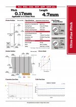
I did find the test probe/pin that might do the job seeing as the clearance between bga and pcb is around 0.2mm
The other part should be fairly easy. Lets see what other people think
 

Attachments

  • P7.jpg
    P7.jpg
    294 KB · Views: 31

Site & Scene News

Popular threads in this forum

General chit-chat
Help Users
  • Xdqwerty @ Xdqwerty:
    also gonna install twilight menu in my r4 flashcard
  • Psionic Roshambo @ Psionic Roshambo:
    One thing that just occurred to me.... The sound on the 2600 sucked less back then the harsh sound we hear now is from infinitely better speakers we have now, back when the 2600 was new speakers produced a almost muffled sound, like CRTs made old graphics look slightly better.
  • Psionic Roshambo @ Psionic Roshambo:
    I wonder if I could recommend that to some emulation devs that perhaps the sound could use some smoothing out to simulate those old TVs
  • Psionic Roshambo @ Psionic Roshambo:
    I think a few of the early systems could benefit from that, at least up to the 8 bit generation, by the 16 bit generation I think TVs had gotten a lot better in almost every way
  • Xdqwerty @ Xdqwerty:
    i dont have an sd card adapter but I have an usb sd card adapter
  • K3Nv2 @ K3Nv2:
    Old people games
  • Xdqwerty @ Xdqwerty:
    its not the one that comes with the r4
  • Xdqwerty @ Xdqwerty:
    doesnt work (my flashcard is from r4isdhc.com)
  • Xdqwerty @ Xdqwerty:
    might install ysmenu first
  • Psionic Roshambo @ Psionic Roshambo:
    Try Wood firmware
  • Psionic Roshambo @ Psionic Roshambo:
    For your R4
  • Psionic Roshambo @ Psionic Roshambo:
    It's old but it's the best firmware out for DS stuff
  • Xdqwerty @ Xdqwerty:
    it says it only works for the original R4, R4i Gold (r4ids.cn), R4iDSN (r4idsn.com) and Acekard R.P.G.
  • Xdqwerty @ Xdqwerty:
    nvm it does support mine
  • Xdqwerty @ Xdqwerty:
    but why choose it over ysmenu @Psionic Roshambo?
  • Xdqwerty @ Xdqwerty:
    bc im stupid?
  • Xdqwerty @ Xdqwerty:
    yea ik im stupid
  • Xdqwerty @ Xdqwerty:
    good night
  • Psionic Roshambo @ Psionic Roshambo:
    Just give it a try, but honestly if you have a 3DS you can play DS games without a card just off the internal SD card
  • Psionic Roshambo @ Psionic Roshambo:
    Slightly slower loading but a bit more convenient
  • BakerMan @ BakerMan:
    guys, my fuckin headphones have an out of place speaker
  • K3Nv2 @ K3Nv2:
    Did you try wearing them?
    B @ btjunior: @Xdqwerty 16