Have you seen this: https://a.aliexpress.com/_msRTyp6Totally agree, waiting for this one to arrive.
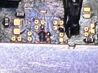
View attachment 374919
Actually no, I was thinking of the "black" version, I imagine it should be similar to the old "corner" adapter. If so, it has a good contact, but I haven't tested them personally.
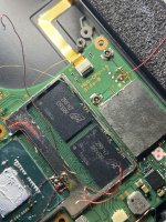
View attachment 374920
There should be as well good adapters from "official HWfly stores", but it's over 10 EUR each, so stencil + hot air is the way.
Looks tempting