Hello,You need to fix that cmd point you broke, you will know its fixed when your switch can boot normally.
I'm still on my torn off CMD signal pads.
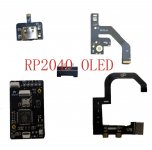
I removed the picofly by removing wires form the picofly, but I let the flex cable in place (I didn't want to touch it).
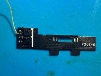
With a magnifier, I saw that the top of the via has been torn off, I saw a rest of the via in the deep of the PCB. I soldered a wire from it to the remaining track of CMD signal.
I turned on the Switch on, and I got a purple/pink screen !
It is better than the black screen than before, but still a not working console...
- Should I remove the flex cable near the processor (CPU wire is "on the air") ?
- Do you know where is the "CMD" signal at the bottom of the PCB ? Maybe I could wire the top to the bottom (because the via is really damaged)
- Maybe I joined a copper layer in the middle of the PCB, but not all layers ?
Thanks for your help