Why not just mask off areas you don't want solder on?
View attachment 374730
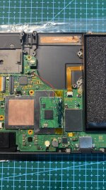
For ground, I don't see any point in soldering to components at all. Soldering to ground points on boards is like a 'choose your own adventure' to me. *Hope you didn't skip the DMM as optional
") *
*May I suggest these:
Last edited by LogicalMadness,