Hacking Hardware Picofly - a HWFLY switch modchip

jkyoho

Well-Known Member
Member
Joined
Sep 2, 2020
Messages
1,270
Trophies
0
Age
39
Location
TORONTO
Website
form.jotform.com
XP
2,201
Country
Canada
You are absolutely right, I just put the cpu at 15 and the RST at 26 and everything works, forgive me for making a whole post looking like a drama queen, NOW IT WORKS, THANKS AND SORRY FOR THE INCONVENIENCE
I saw you reversed the RST and CPU wiring since last device/videos few days ago, but end up you did same thing on the new one. :wacko:
 

Dee87

Well-Known Member
Member
Joined
Mar 19, 2023
Messages
1,139
Trophies
1
XP
1,575
Country
Germany
Hello, I come to you once again. I bought a Zelda edition console, I proceeded to test it, everything worked fine, I took it apart and started to install picofly, once installed it gave me a clk/CMD error with fw2.67 (the colors of both errors are very similar, so I don't I knew how to identify which one it was exactly) I proceeded to change the wiring of both points and it was still the same, a user suggested I use the most recent fw, I did, now apparently it gives an error in RST, I changed the RST cable to verify that there was continuity in both points and still it keeps giving me an error, what seems strange to me is that clk and cmd give me strange values and I don't know why, if someone can help me please I would appreciate it 🥺🥺🥺 
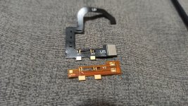
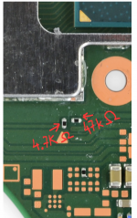
seriously I'm desperate, I already changed the wiring it originally had. I want to cry, the images are of the values in clk and cmd
bro swap the rst and cpu lines then it will work properly.

edit : well just someone already gave u the answer and u did it Xd
 

LogicalMadness

Well-Known Member
Member
Joined
Nov 3, 2014
Messages
287
Trophies
0
Age
41
XP
690
Country
United States
Whre is this resistor?

This is you:
love-life.gif
 

Amira

Member
Newcomer
Joined
May 9, 2023
Messages
5
Trophies
0
Age
23
XP
25
Country
Russia
Please tell me, is it necessary to smear the thermal paste back on the metal shield and the reverse side of the thermotube? If not, does it affect heat dissipation?

Please forgive me for my English I use Google Translate
 
  • Like
Reactions: Danook28

QuiTim

Well-Known Member
Member
Joined
Mar 30, 2023
Messages
754
Trophies
0
XP
1,153
Country
Albania
Not of the screen.
The motherboard with the pico.
And did you check for @Dee87 advice on checking the resistor values?

Edit - hmmm everythings disconnected now but still pink. Let me do some research on this pink/purple screen.
I think this is the default stance now of alot of guys when entering this thread :D
 

Attachments

  • 226.gif
    226.gif
    1.8 MB · Views: 22

Dee87

Well-Known Member
Member
Joined
Mar 19, 2023
Messages
1,139
Trophies
1
XP
1,575
Country
Germany
Please tell me, is it necessary to smear the thermal paste back on the metal shield and the reverse side of the thermotube? If not, does it affect heat dissipation?

Please forgive me for my English I use Google Translate
yes it is i mean u can leave it off but i bet with u u will probally have overheating problems Xd
Post automatically merged:

I think this is the default stance now of alot of guys when entering this thread :D
So true . we should add to the thread name (If u Have issues also post a Picture) Xd
 

QuiTim

Well-Known Member
Member
Joined
Mar 30, 2023
Messages
754
Trophies
0
XP
1,153
Country
Albania
Please tell me, is it necessary to smear the thermal paste back on the metal shield and the reverse side of the thermotube? If not, does it affect heat dissipation?

Please forgive me for my English I use Google Translate
Dee87 already answerd it but the basic principle when you want to put back a piece of equipment you work your way back from the disassembly so in this case you removed thermal paste-you put back the thermal paste...
This does not apply to Pico, so you soldered in the Pico-you dont remove the Pico :D
 
  • Haha
Reactions: Dee87

LogicalMadness

Well-Known Member
Member
Joined
Nov 3, 2014
Messages
287
Trophies
0
Age
41
XP
690
Country
United States
Please tell me, is it necessary to smear the thermal paste back on the metal shield and the reverse side of the thermotube? If not, does it affect heat dissipation?

Please forgive me for my English I use Google Translate

Default stance is to never touch that PARTICULAR layer of paste (edit: as in- don't remove the paste and just stack the heatsink on the shield (paste to paste) when working on switch). Personally, I replace it with 0.5mm cheap thermal pads. It really doesn't do much though, you would PROBABLY be fine if you removed and then did not replace THIS PARTICULAR layer of paste. All other layers are absolutely needed.
 

LogicalMadness

Well-Known Member
Member
Joined
Nov 3, 2014
Messages
287
Trophies
0
Age
41
XP
690
Country
United States
Default stance is to never touch that PARTICULAR layer of paste (edit: as in- don't remove the paste and just stack the heatsink on the shield (paste to paste) when working on switch). Personally, I replace it with 0.5mm cheap thermal pads. It really doesn't do much though, you would PROBABLY be fine if you removed and then did not replace THIS PARTICULAR layer of paste. All other layers are absolutely needed.

I mean, has anyone else actually, REALLY, looked at the Switch's 'air flow'? It's a joke! SO many dead P13s from dusty only-dock-Switchs...
Post automatically merged:

yes it is i mean u can leave it off but i bet with u u will probally have overheating problems Xd
Post automatically merged:
Meh, I disagree on that layer of paste causing an overheat

So true . we should add to the thread name (If u Have issues also post a Picture) Xd
I read it that @QuiTim means the GIF is the default stance of us.
 
  • Like
Reactions: jkyoho

QuiTim

Well-Known Member
Member
Joined
Mar 30, 2023
Messages
754
Trophies
0
XP
1,153
Country
Albania
I mean, has anyone else actually, REALLY, looked at the Switch's 'air flow'? It's a joke! SO many dead P13s from dusty only-dock-Switchs...
Post automatically merged:


Meh, I disagree on that layer of paste causing an overheat


I read it that @QuiTim means the GIF is the default stance of us.
You are right, i was refering to facepalm gif.
But Dee87 is right, posting pictures/videos by default when asking for help would save everybody alot of time
 

LogicalMadness

Well-Known Member
Member
Joined
Nov 3, 2014
Messages
287
Trophies
0
Age
41
XP
690
Country
United States
You are right, i was refering to facepalm gif.
But Dee87 is right, posting pictures/videos by default when asking for help would save everybody alot of time

It COULD save time, but so would responsibly using 'search skills'.

napoleon-dynamite.gif


Lol, saving time by spending time writing something a lot still won't read XD

Poor @lightninjay knows those feels more than most though, some people need to be hand-held so much that you end up dragging them (see my earlier GIF). Recently also realized (hence the "poor" earlier), to truly attain the "Definitive" part of the guide's title, he needs to, SPECIFICALLY, read ALL the redundant questions (AND test answering them), if he ever hopes to head them all off within the guide. In other words, as far as I'm concerned, @lightninjay is one of several 'gods o' the thread', just saying XD

So many great GIFs for my reactions to temper posts, though, but I think this may be the best for this thread in particular:
face-palm.gif
 

CodyRoseman

Active Member
Newcomer
Joined
Apr 27, 2023
Messages
41
Trophies
0
Age
27
XP
101
Country
Australia
Here is a CPU flex for Mariko devices, with Dual Independent MOSFETs. I put small pads for sp1 and sp2 if you just want to run wires instead of placing the flex over the capacitors.

also ignore the small circles in the cutouts, that's just the 3d viewer not cutting out the copper from plated through holes.

Kicad project and gerbers:
https://drive.google.com/drive/folders/1YPrlNqbp0VJ8IM3nWb1fSZJKgaQMFjxY


pcbnew_tYafdgR3EV.png
FlexOLEDSingleBack.png
 
Last edited by CodyRoseman,

rsilveira1991

Active Member
Newcomer
Joined
Apr 16, 2023
Messages
29
Trophies
0
Age
33
XP
93
Country
Brazil
May I know what video is it?

Post automatically merged:

Here is a CPU flex for Mariko devices, with Dual Independent MOSFETs. I put small pads for sp1 and sp2 if you just want to run wires instead of placing the flex over the capacitors.

also ignore the small circles in the cutouts, that's just the 3d viewer not cutting out the copper from plated through holes.

Kicad project and gerbers:
https://drive.google.com/drive/folders/1YPrlNqbp0VJ8IM3nWb1fSZJKgaQMFjxY


View attachment 374793
I like the Idea that put the CPU point at the Right.
I think I will try it at next Revision.
 

Site & Scene News

Popular threads in this forum

General chit-chat
Help Users
  • No one is chatting at the moment.
    HiradeGirl @ HiradeGirl: Have a nice day. Life. Week. Month. year.