


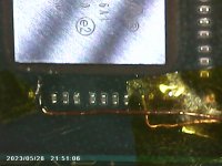
Oh snap! Just when i thought i was getting somewhere. Re - the 3.3v point, thats the point im already using for the Lite!?Thats an inductor, it is supposed to be shorted i think (if we are talking about the circled one)
You are using an out of date browser. It may not display this or other websites correctly.
You should upgrade or use an alternative browser.
You should upgrade or use an alternative browser.
Staff Posts
Recent threadmarks
sharing files
Important Posts
Recent threadmarks
Firmwares
My bad on the 3.3. Thats GND connected there, you are OKOh snap! Just when i thought i was getting somewhere. Re - the 3.3v point, thats the point im already using for the Lite!?

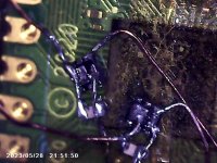
No probs. Got any theories on what i could be? The most I can think is either short or emmc. What ya guys thnik?My bad on the 3.3. Thats GND connected there, you are OK

I'm like 95% on emmc...if it was a short you would have bigger problems i thinkNo probs. Got any theories on what i could be? The most I can think is either short or emmc. What ya guys thnik?
thanks, going to research emmc stuff. more thank likely its that.I'm like 95% on emmc...if it was a short you would have bigger problems i think
Code is ==* CPU always reach BCT check (no glitch reaction, check mosfet)Just did an install and this is the code I’m getting. Used the mosfet method. The blinks are yellow. Any help would be appreciated
Read the guide in my signature.Just did an install and this is the code I’m getting. Used the mosfet method. The blinks are yellow. Any help would be appreciated
==* CPU always reach BCT check (no glitch reaction, check mosfet)Just did an install and this is the code I’m getting. Used the mosfet method. The blinks are yellow. Any help would be appreciated
- Joined
- Sep 2, 2020
- Messages
- 1,269
- Trophies
- 0
- Age
- 39
- Location
- TORONTO
- Website
- form.jotform.com
- XP
- 2,200
- Country

2 long 1 short, show your mosfet workJust did an install and this is the code I’m getting. Used the mosfet method. The blinks are yellow. Any help would be appreciated

Just get another pi pico, flash 2.74, and this time just remove the transistor for dat0 solder point in pico board, then assembled all the wire, then power on.. if like you said that your switch board soldering in fine then it should boot to sdcard screen.
Pi Pico is a rather tricky, but ive done multiple units with Pi Pico and in the process ive lost/burn/broke 4 pico boards.
yep dont add pain to yourself, buy new one as simple as that
Hello! I managed to replace the pico with a new one so I can use the latest v2.74 and now I can see the error clearly!! It's ==* which means CPU always reach BCT check (no glitch reaction, check mosfet). I desoldered and re-soldered the two MOSFETs multiple times and replaced them just in case they were bad, but I keep getting the same error and then the Switch boots normally, so idk what to check.
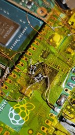
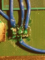
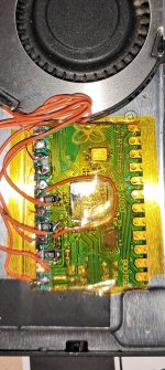
Here I attach photos of my setup, sorry if it looks a bit messy, I can guarantee that is well insulated and the MOSFETs seem well soldered (even if it's not clear in the images).Any detailed setup photos?
Attachments
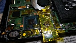
I'm sorry, but you need to improve your soldering skill if you want to cleanly perform this mod.Hello! I managed to replace the pico with a new one so I can use the latest v2.74 and now I can see the error clearly!! It's ==* which means CPU always reach BCT check (no glitch reaction, check mosfet). I desoldered and re-soldered the two MOSFETs multiple times and replaced them just in case they were bad, but I keep getting the same error and then the Switch boots normally, so idk what to check.
Here I attach photos of my setup, sorry if it looks a bit messy, I can guarantee that is well insulated and the MOSFETs seem well soldered (even if it's not clear in the images).
I know hehe, I was hoping it could work out as long as it's physically soldered.I'm sorry, but you need to improve your soldering skill if you want to cleanly perform this mod.
I would love to do it better but the issue I had with the MOSFET itself is that it's really hard to keep the solder in its tiny pins, it gets out really easily when I try to solder the cables, so I end up putting too much solder in order to at least keep it there. Also, if I'm too near a pin I already soldered, the temperature ends up desoldering it again. I lowered the soldering iron temperature but helped just a bit.
Any tips or recommendations for making it cleaner without ending up so fragile?
Btw I'm seriously considering replacing the MOSFET with a bigger alternative.

Hello! I managed to replace the pico with a new one so I can use the latest v2.74 and now I can see the error clearly!! It's ==* which means CPU always reach BCT check (no glitch reaction, check mosfet). I desoldered and re-soldered the two MOSFETs multiple times and replaced them just in case they were bad, but I keep getting the same error and then the Switch boots normally, so idk what to check.
Here I attach photos of my setup, sorry if it looks a bit messy, I can guarantee that is well insulated and the MOSFETs seem well soldered (even if it's not clear in the images).
In Oled i experience the same.
You might try to increase the resistor of CMD/CLK/Dat0 to around 100ohm. Usually by add another 47ohm.
Last edited by abal1000x,
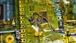
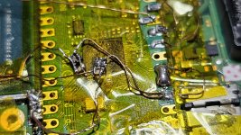
jays right. It takes practise. You just have to git gud. Heres my method i did recently with a 10k pull down resistor bridging the mosfets' gate and source Covering each point in solder mask. Patience is king otherwise it won't workI know hehe, I was hoping it could work out as long as it's physically soldered.
I would love to do it better but the issue I had with the MOSFET itself is that it's really hard to keep the solder in its tiny pins, it gets out really easily when I try to solder the cables, so I end up putting too much solder in order to at least keep it there. Also, if I'm too near a pin I already soldered, the temperature ends up desoldering it again. I lowered the soldering iron temperature but helped just a bit.
Any tips or recommendations for making it cleaner without ending up so fragile?
Btw I'm seriously considering replacing the MOSFET with a bigger alternative.
Attachments
Just search in here theres lot of successfull mosfet alt.I know hehe, I was hoping it could work out as long as it's physically soldered.
I would love to do it better but the issue I had with the MOSFET itself is that it's really hard to keep the solder in its tiny pins, it gets out really easily when I try to solder the cables, so I end up putting too much solder in order to at least keep it there. Also, if I'm too near a pin I already soldered, the temperature ends up desoldering it again. I lowered the soldering iron temperature but helped just a bit.
Any tips or recommendations for making it cleaner without ending up so fragile?
Btw I'm seriously considering replacing the MOSFET with a bigger alternative.
This is my note (from message post in this thread):
AON7400A
Not Work/ Not Strong Enough to Glitch
It give false positive so cannot work reliably, one unit returned from customer with systomp can only boot to stock.
AON6414A
Not Work/ Not Strong Enough to Glitch
AON S36312
Works, Reliable But large package 5x6, Single Mosfet Install
AON 6512
Works, Reliable But large package 5x6, Single Mosfet Install
AON 6792
Works, Reliable But large package 5x6, Single Mosfet Install
FDMC 7672
Works, Reliable, Perfect 3x3 package, Single Mosfet Install
did you have this ==* code?Try to check the dat0, maybe its SC with others.
In Oled i experience the same.
You might try to increase the resistor of CMD/CLK/Dat0 to around 100ohm. Usually by add another 47ohm.

for me if thats happens most of the times its the mosfets installations, try using flex v1 or v2 so much easier and took afew second to instalHello! I managed to replace the pico with a new one so I can use the latest v2.74 and now I can see the error clearly!! It's ==* which means CPU always reach BCT check (no glitch reaction, check mosfet). I desoldered and re-soldered the two MOSFETs multiple times and replaced them just in case they were bad, but I keep getting the same error and then the Switch boots normally, so idk what to check.
Here I attach photos of my setup, sorry if it looks a bit messy, I can guarantee that is well insulated and the MOSFETs seem well soldered (even if it's not clear in the images).
did you have this ==* code?
I use flex cable, and double check it. Its not mosfet.
And my instinct tell me its the dat0 adapter, since i experiment on it.
And its really is the dat0 adapter.
Last edited by abal1000x,
Buy bigger mosfet 5x6 mm package should be easy enough.I know hehe, I was hoping it could work out as long as it's physically soldered.
I would love to do it better but the issue I had with the MOSFET itself is that it's really hard to keep the solder in its tiny pins, it gets out really easily when I try to solder the cables, so I end up putting too much solder in order to at least keep it there. Also, if I'm too near a pin I already soldered, the temperature ends up desoldering it again. I lowered the soldering iron temperature but helped just a bit.
Any tips or recommendations for making it cleaner without ending up so fragile?
Btw I'm seriously considering replacing the MOSFET with a bigger alternative.
Also buy Wire Wrapping, you use all enamel and with that quality of soldering there is a high chance of cold joint in those point.
also please isolate Dat0 point from ground thats not safe at all.
Use cable jumper to isolate it.
Attachments
Last edited by cgtchy0412,
Similar threads
- Replies
- 3
- Views
- 877
- Replies
- 42
- Views
- 5K
- Replies
- 5
- Views
- 1K
- Replies
- 6
- Views
- 2K
- Replies
- 8
- Views
- 2K
Site & Scene News
New Hot Discussed
-
-
62K views
Nintendo Switch firmware 18.0.0 has been released
It's the first Nintendo Switch firmware update of 2024. Made available as of today is system software version 18.0.0, marking a new milestone. According to the patch... -
24K views
Atmosphere CFW for Switch updated to pre-release version 1.7.0, adds support for firmware 18.0.0
After a couple days of Nintendo releasing their 18.0.0 firmware update, @SciresM releases a brand new update to his Atmosphere NX custom firmware for the Nintendo...by ShadowOne333 107 -
20K views
Wii U and 3DS online services shutting down today, but Pretendo is here to save the day
Today, April 8th, 2024, at 4PM PT, marks the day in which Nintendo permanently ends support for both the 3DS and the Wii U online services, which include co-op play...by ShadowOne333 179 -
16K views
GBAtemp Exclusive Introducing tempBOT AI - your new virtual GBAtemp companion and aide (April Fools)
Hello, GBAtemp members! After a prolonged absence, I am delighted to announce my return and upgraded form to you today... Introducing tempBOT AI 🤖 As the embodiment... -
13K views
Pokemon fangame hosting website "Relic Castle" taken down by The Pokemon Company
Yet another casualty goes down in the never-ending battle of copyright enforcement, and this time, it hit a big website which was the host for many fangames based and...by ShadowOne333 66 -
13K views
The first retro emulator hits Apple's App Store, but you should probably avoid it
With Apple having recently updated their guidelines for the App Store, iOS users have been left to speculate on specific wording and whether retro emulators as we... -
13K views
MisterFPGA has been updated to include an official release for its Nintendo 64 core
The highly popular and accurate FPGA hardware, MisterFGPA, has received today a brand new update with a long-awaited feature, or rather, a new core for hardcore...by ShadowOne333 54 -
12K views
Delta emulator now available on the App Store for iOS
The time has finally come, and after many, many years (if not decades) of Apple users having to side load emulator apps into their iOS devices through unofficial...by ShadowOne333 95 -
10K views
"TMNT: The Hyperstone Heist" for the SEGA Genesis / Mega Drive gets a brand new DX romhack with new features
The romhacking community is always a source for new ways to play retro games, from completely new levels or stages, characters, quality of life improvements, to flat...by ShadowOne333 36 -
10K views
Anbernic announces RG35XX 2024 Edition retro handheld
Retro handheld manufacturer Anbernic is releasing a refreshed model of its RG35XX handheld line. This new model, named RG35XX 2024 Edition, features the same...
-
-
-
225 replies
Nintendo Switch firmware 18.0.0 has been released
It's the first Nintendo Switch firmware update of 2024. Made available as of today is system software version 18.0.0, marking a new milestone. According to the patch...by Chary -
179 replies
Wii U and 3DS online services shutting down today, but Pretendo is here to save the day
Today, April 8th, 2024, at 4PM PT, marks the day in which Nintendo permanently ends support for both the 3DS and the Wii U online services, which include co-op play...by ShadowOne333 -
169 replies
GBAtemp Exclusive Introducing tempBOT AI - your new virtual GBAtemp companion and aide (April Fools)
Hello, GBAtemp members! After a prolonged absence, I am delighted to announce my return and upgraded form to you today... Introducing tempBOT AI 🤖 As the embodiment...by tempBOT -
107 replies
Atmosphere CFW for Switch updated to pre-release version 1.7.0, adds support for firmware 18.0.0
After a couple days of Nintendo releasing their 18.0.0 firmware update, @SciresM releases a brand new update to his Atmosphere NX custom firmware for the Nintendo...by ShadowOne333 -
96 replies
The first retro emulator hits Apple's App Store, but you should probably avoid it
With Apple having recently updated their guidelines for the App Store, iOS users have been left to speculate on specific wording and whether retro emulators as we...by Scarlet -
95 replies
Delta emulator now available on the App Store for iOS
The time has finally come, and after many, many years (if not decades) of Apple users having to side load emulator apps into their iOS devices through unofficial...by ShadowOne333 -
67 replies
Nintendo Switch firmware update 18.0.1 has been released
A new Nintendo Switch firmware update is here. System software version 18.0.1 has been released. This update offers the typical stability features as all other...by Chary -
66 replies
Pokemon fangame hosting website "Relic Castle" taken down by The Pokemon Company
Yet another casualty goes down in the never-ending battle of copyright enforcement, and this time, it hit a big website which was the host for many fangames based and...by ShadowOne333 -
54 replies
MisterFPGA has been updated to include an official release for its Nintendo 64 core
The highly popular and accurate FPGA hardware, MisterFGPA, has received today a brand new update with a long-awaited feature, or rather, a new core for hardcore...by ShadowOne333 -
53 replies
Nintendo "Indie World" stream announced for April 17th, 2024
Nintendo has recently announced through their social media accounts that a new Indie World stream will be airing tomorrow, scheduled for April 17th, 2024 at 7 a.m. PT...by ShadowOne333
-
