


yeah i tried that method but found it to be a bit worse atleast for me (but to each of their own lol) Nothing i was just saying if my mosfet had any bridges that i didnt notice. but you said it looks good so thanks i appriciate the amazing guides youve made for this community and the help youve put into this fourmIf it works for you, then great, but I'm still more partial to this wayView attachment 374573
You are using an out of date browser. It may not display this or other websites correctly.
You should upgrade or use an alternative browser.
You should upgrade or use an alternative browser.
Picofly AIO Thread
- Thread starter Adran_Marit
- Start date
- Views 513,850
- Replies 3,351
- Likes 60
I did say "if it works for you", I have a small fear of the points within the red circle bridging if you don't carefully insulate them from one another.yeah i tried that method but found it to be a bit worse atleast for me (but to each of their own lol) Nothing i was just saying if my mosfet had any bridges that i didnt notice. but you said it looks good so thanks i appriciate the amazing guides youve made for this community and the help youve put into this fourm

Have the exact same issue. Looking for the Dat points for short found nothing but found a cap near the ground point (the cap for the lite). Near it is a chip. Not sure if that went out or the Cap went out. I used 2.7 firmware and feel that what caused it. Discorder users say that bricks the console, i might agree with them however, i do get pico logo but cant get elsewhere just like you. So not sure right now. Any updates? Does this cap short for you too?As I understand it (someone please correct me if I'm wrong) - The picofly writes to emmc (Normal BCT & SafeMode BCT & an unused section) - so it can't just be removed.... because the BCT (Boot Configuration Table) has been modified to point to the custom payload (not referring to payload.bin).
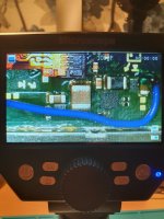
Mine still gets the no sd card if there is no sd card.... and I've managed to confirm that the glitch and boot sequence is working by using "ums-loader" as my payload.bin.
Just can't get in to Hekate.
Attachments

I am backtracking through the post and I see that you refered to this point as 3v3.Thanks.I understand that this component has made contact with the resistor on the right and has burned, can it be replaced? what is it called? thanksView attachment 374534
So lets clear this out, the point in your photo is supposed to be GND.
Did you solder 3v3 there or you just mistyped name in your message?
If you soldered 3v3 there then you have a big problem.
If you soldered GND, you are OK since thats the point it should be used for GND.
Everything can always be revived in my eyes. Is the juice worth the squeeze though?The slims will probably be converted to super slims as the cd controllers are dead and the ps1 I'm not sure can be revived

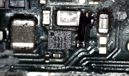
So - I've just inspected in that area with the microscope - and everything seemed okay - till I did another cleaning pass with some IPA and then noticed one of the parts looks a little odd - not a capacitor though.Have the exact same issue. Looking for the Dat points for short found nothing but found a cap near the ground point (the cap for the lite). Near it is a chip. Not sure if that went out or the Cap went out. I used 2.7 firmware and feel that what caused it. Discorder users say that bricks the console, i might agree with them however, i do get pico logo but cant get elsewhere just like you. So not sure right now. Any updates? Does this cap short for you too?
Perhaps someone can shed some light on what the part in this spot is?
(This is a reference image - on mine the part is blown - when cleaning the whole top came off and it crumbled).
Nothing left of that part on my board

Last edited by floxcap,

With the wires shortened as humanly possible (the Pico positioned on the top of the EMMC) and two caps with single MOSFET it still behaves the same way. Time to try the SDA/SCL option. Those are only data connections, so 0.1mm enamel wire should be fine, right? Does it matter how the wires are routed, on the back of the MB or through the front; it seems to be the same to me, but then again I'll be doing it for a first time so no idea if it makes a difference?I intentionally used only one of the available data pads. I thought, if I accidentally rip the pad (a lot of people did) I'll have a backup to fall on without needing to resort to trace repairs. Now that I know the connections are decent I can mask the wires to the board and call it a day. I need to replace the MOSFET anyway (don't ask why
Diode? Hence the arrow-line symbol?So - I've just inspected in that area with the microscope - and everything seemed okay - till I did another cleaning pass with some IPA and then noticed one of the parts looks a little odd - not a capacitor though.
Perhaps someone can shed some light on what the part in this spot is?
(This is a reference image - on mine the part is blown - when cleaning the whole top came off and it crumbled).
Nothing left of that part on my board
View attachment 374622View attachment 374628
Nevermind that previous observation of mine, @QuiTim says its most likely an inductor and not a cap and they usually give negatives in diode mode on multimeter. I honestly think its bricked (atleast mine). My theory is, the emmc got corrupted with the bad firmware and will not boot into stage 1. Only way I know how to fix that is if you can get into hekate to restore a back up. But can't do that because couldn't make a backup in the first place OR two, get a donor emmc but even that way probably won't work because....what emmc am i going to clone it with? Shyza!So - I've just inspected in that area with the microscope - and everything seemed okay - till I did another cleaning pass with some IPA and then noticed one of the parts looks a little odd - not a capacitor though.
Perhaps someone can shed some light on what the part in this spot is?
(This is a reference image - on mine the part is blown - when cleaning the whole top came off and it crumbled).
Nothing left of that part on my board
View attachment 374622View attachment 374628
Diode? Hence the arrow-line symbol?
Doh. I feel silly for not noticing that.
THB - I was thinking that looked like some sort of boost/buck converted (just guessing based on the layout pattern / inductor etc). So yeah - diode would make sense.
I've probably got something suitable to replace it (but it'd be a guess for the specifics).
Perhaps I could use one of these:
Schottky 2A 30V 380pF
??
Last edited by floxcap,

Sorry, you are right, it was my typing mistake, there I soldered GND from the 2040 to that point of the resistor, then why does it seem to have burned? maybe a short with the integrated on the left? I'm really lost now, should I replace the resistor and the integrated? thanksI am backtracking through the post and I see that you refered to this point as 3v3.
So lets clear this out, the point in your photo is supposed to be GND.
Did you solder 3v3 there or you just mistyped name in your message?
If you soldered 3v3 there then you have a big problem.
If you soldered GND, you are OK since thats the point it should be used for GND.
Post automatically merged:
As I understand it, this component was burned when contacting the resistor where I soldered the GND, what is it called? is it easy to replace? thank you.
Post automatically merged:
I think I have the same problem as you, it seems that when I soldered the GND made contact with that component and burned, I saw smoke coming out of that area.Doh. I feel silly for not noticing that.
THB - I was thinking that looked like some sort of boost/buck converted (just guessing based on the layout pattern / inductor etc). So yeah - diode would make sense.
I've probably got something suitable to replace it (but it'd be a guess for the specifics).
Perhaps I could use one of these:
Schottky 2A 30V 380pF
??
In microscope it doesn't look bad but if it smells burnt, what can I replace it with? thanks.
Last edited by kapranos,
Sorry, you are right, it was my typing mistake, there I soldered GND from the 2040 to that point of the resistor, then why does it seem to have burned? maybe a short with the integrated on the left? I'm really lost now, should I replace the resistor and the integrated? thanks
Post automatically merged:
As I understand it, this component was burned when contacting the resistor where I soldered the GND, what is it called? is it easy to replace? thank you.View attachment 374676
Post automatically merged:
I think I have the same problem as you, it seems that when I soldered the GND made contact with that component and burned, I saw smoke coming out of that area.
In microscope it doesn't look bad but if it smells burnt, what can I replace it with? thanks.
View attachment 374677
I Think - what's been pointed out to me - that it is probably a diode.
I've done quite a bit of searching and haven't found any direct information on it yet.
There seems to be a few places around that are selling "switch lite diode".
I suspect though that it might be a schottky diode of some value - hopefully that means that the value doesn't matter too much - so I don't have one on hand that will fit - but I'm going to test my theory (hopefully) tonight with an ugly hack:
(Schottky 2A 30V 380pF - is all I have on hand).
Attachments

After managing to mod my Switch Lite quite easily, I think I messed up my patched V1. All went smooth until the 3v3 point on the cap. I bridged the contact to the cap next to it and to remove the bridge I then had to remove the 3v3 cap from the board. During this process the cap got pretty destroyed: No lead on one of the sides and change in color. So not usable anymore. The solder pads still seem to be fine, no bridge.
Is it possible/save to run the Switch without this cap or is there another cap, that I could source somewhere else?
According to this here it is a 2.2µf 10V MLCC, so there would still be the alternative to just order some of these off the shelf.

Is it possible/save to run the Switch without this cap or is there another cap, that I could source somewhere else?
According to this here it is a 2.2µf 10V MLCC, so there would still be the alternative to just order some of these off the shelf.
You should solder 3v3 on emmc board. And I think that Switch works without this capAfter managing to mod my Switch Lite quite easily, I think I messed up my patched V1. All went smooth until the 3v3 point on the cap. I bridged the contact to the cap next to it and to remove the bridge I then had to remove the 3v3 cap from the board. During this process the cap got pretty destroyed: No lead on one of the sides and change in color. So not usable anymore. The solder pads still seem to be fine, no bridge.
Is it possible/save to run the Switch without this cap or is there another cap, that I could source somewhere else?
According to this here it is a 2.2µf 10V MLCC, so there would still be the alternative to just order some of these off the shelf.
View attachment 374683
Attachments
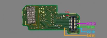
It seems that this inductor is damaged, how could I measure its values and what should they be? thanksThe inductor close to 3v3 seems damaged (might be bad photo)
Also check for short on the resistor side in pico
Don't know the values but it should be this one: https://www.aliexpress.com/item/1005002702445165.htmlIt seems that this inductor is damaged, how could I measure its values and what should they be? thanks
Thank you. So no permanent damage or unstability to be expected without the cap?You should solder 3v3 on emmc board. And I think that Switch works without this cap
I don't know the long term consequences. You should probably replace the cap in meantime if possible.Thank you. So no permanent damage or unstability to be expected without the cap?

Hello yes hi I accidentally dropped my Switch through a wood chipper plz revive itEverything can always be revived in my eyes. Is the juice worth the squeeze though?
No problem, please contact us for reverse wood chipper procedureHello yes hi I accidentally dropped my Switch through a wood chipper plz revive it
Post automatically merged:
after 3h of research (I have a mild case of ocd for these kind of thingsI Think - what's been pointed out to me - that it is probably a diode.
I've done quite a bit of searching and haven't found any direct information on it yet.
There seems to be a few places around that are selling "switch lite diode".
I suspect though that it might be a schottky diode of some value - hopefully that means that the value doesn't matter too much - so I don't have one on hand that will fit - but I'm going to test my theory (hopefully) tonight with an ugly hack:
(Schottky 2A 30V 380pF - is all I have on hand).View attachment 374682
) it seems to be a 5.6V 200mA schottkyAttachments
Last edited by QuiTim,
Similar threads
- Replies
- 8
- Views
- 935
- Replies
- 8
- Views
- 3K
- Replies
- 3
- Views
- 623
- Replies
- 10
- Views
- 2K
- Replies
- 1
- Views
- 2K
Site & Scene News
New Hot Discussed
-
-
62K views
Nintendo Switch firmware 18.0.0 has been released
It's the first Nintendo Switch firmware update of 2024. Made available as of today is system software version 18.0.0, marking a new milestone. According to the patch... -
23K views
Atmosphere CFW for Switch updated to pre-release version 1.7.0, adds support for firmware 18.0.0
After a couple days of Nintendo releasing their 18.0.0 firmware update, @SciresM releases a brand new update to his Atmosphere NX custom firmware for the Nintendo...by ShadowOne333 98 -
20K views
Wii U and 3DS online services shutting down today, but Pretendo is here to save the day
Today, April 8th, 2024, at 4PM PT, marks the day in which Nintendo permanently ends support for both the 3DS and the Wii U online services, which include co-op play...by ShadowOne333 179 -
16K views
GBAtemp Exclusive Introducing tempBOT AI - your new virtual GBAtemp companion and aide (April Fools)
Hello, GBAtemp members! After a prolonged absence, I am delighted to announce my return and upgraded form to you today... Introducing tempBOT AI 🤖 As the embodiment... -
13K views
Pokemon fangame hosting website "Relic Castle" taken down by The Pokemon Company
Yet another casualty goes down in the never-ending battle of copyright enforcement, and this time, it hit a big website which was the host for many fangames based and...by ShadowOne333 66 -
13K views
The first retro emulator hits Apple's App Store, but you should probably avoid it
With Apple having recently updated their guidelines for the App Store, iOS users have been left to speculate on specific wording and whether retro emulators as we... -
12K views
MisterFPGA has been updated to include an official release for its Nintendo 64 core
The highly popular and accurate FPGA hardware, MisterFGPA, has received today a brand new update with a long-awaited feature, or rather, a new core for hardcore...by ShadowOne333 54 -
12K views
Delta emulator now available on the App Store for iOS
The time has finally come, and after many, many years (if not decades) of Apple users having to side load emulator apps into their iOS devices through unofficial...by ShadowOne333 95 -
10K views
"TMNT: The Hyperstone Heist" for the SEGA Genesis / Mega Drive gets a brand new DX romhack with new features
The romhacking community is always a source for new ways to play retro games, from completely new levels or stages, characters, quality of life improvements, to flat...by ShadowOne333 36 -
10K views
Anbernic announces RG35XX 2024 Edition retro handheld
Retro handheld manufacturer Anbernic is releasing a refreshed model of its RG35XX handheld line. This new model, named RG35XX 2024 Edition, features the same...
-
-
-
225 replies
Nintendo Switch firmware 18.0.0 has been released
It's the first Nintendo Switch firmware update of 2024. Made available as of today is system software version 18.0.0, marking a new milestone. According to the patch...by Chary -
179 replies
Wii U and 3DS online services shutting down today, but Pretendo is here to save the day
Today, April 8th, 2024, at 4PM PT, marks the day in which Nintendo permanently ends support for both the 3DS and the Wii U online services, which include co-op play...by ShadowOne333 -
169 replies
GBAtemp Exclusive Introducing tempBOT AI - your new virtual GBAtemp companion and aide (April Fools)
Hello, GBAtemp members! After a prolonged absence, I am delighted to announce my return and upgraded form to you today... Introducing tempBOT AI 🤖 As the embodiment...by tempBOT -
98 replies
Atmosphere CFW for Switch updated to pre-release version 1.7.0, adds support for firmware 18.0.0
After a couple days of Nintendo releasing their 18.0.0 firmware update, @SciresM releases a brand new update to his Atmosphere NX custom firmware for the Nintendo...by ShadowOne333 -
96 replies
The first retro emulator hits Apple's App Store, but you should probably avoid it
With Apple having recently updated their guidelines for the App Store, iOS users have been left to speculate on specific wording and whether retro emulators as we...by Scarlet -
95 replies
Delta emulator now available on the App Store for iOS
The time has finally come, and after many, many years (if not decades) of Apple users having to side load emulator apps into their iOS devices through unofficial...by ShadowOne333 -
66 replies
Pokemon fangame hosting website "Relic Castle" taken down by The Pokemon Company
Yet another casualty goes down in the never-ending battle of copyright enforcement, and this time, it hit a big website which was the host for many fangames based and...by ShadowOne333 -
61 replies
Nintendo Switch firmware update 18.0.1 has been released
A new Nintendo Switch firmware update is here. System software version 18.0.1 has been released. This update offers the typical stability features as all other...by Chary -
54 replies
MisterFPGA has been updated to include an official release for its Nintendo 64 core
The highly popular and accurate FPGA hardware, MisterFGPA, has received today a brand new update with a long-awaited feature, or rather, a new core for hardcore...by ShadowOne333 -
53 replies
Nintendo "Indie World" stream announced for April 17th, 2024
Nintendo has recently announced through their social media accounts that a new Indie World stream will be airing tomorrow, scheduled for April 17th, 2024 at 7 a.m. PT...by ShadowOne333
-
Popular threads in this forum
General chit-chat
-
 AncientBoi
Loading…
AncientBoi
Loading…
-
-
-
-
-
-
-
-
-
 @
NinStar:
quite ironic that brawlhalla has a far superior netcode compared to smash bros ultimate while offering free online play with crossplay support
@
NinStar:
quite ironic that brawlhalla has a far superior netcode compared to smash bros ultimate while offering free online play with crossplay support -
-
-
-
-
-
-
-
-
-
-
-
-
-
-
-


 (
(


