


If you are on the new fw I guess it's saying ==* so you need to check mosfet, you might have a loose connection
You are using an out of date browser. It may not display this or other websites correctly.
You should upgrade or use an alternative browser.
You should upgrade or use an alternative browser.
Staff Posts
Recent threadmarks
sharing files
Important Posts
Recent threadmarks
Firmwares


It's to rebuild the firmware.please do not use your v1 backup on your lite.
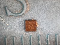
You can use it. I also used this one.Anyone know if I can use this mosfet for the CPU? It’s a “IRFHS8342TRPBF”

Hi everyone,
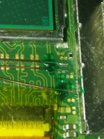
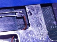
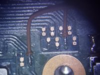
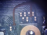
First of all I'm sorry for my English, but I need your help, because during the installation of the picofly I had a problem, two soldering points have been jumped by moving the wires.
I wanted to ask you if you know any alternative soldering point for a Switch Lite from point D0 or if you know any technique to try to repair the points, I attach a photo so you can see in more detail.
Any help would be wonderful
Thank you very much

Like with the oled clk point if your not careful and short the pad you can end up with bsod so it does sound like the issue some have had with lite installs is to do with killing the emmc.
To avoid it I like to cover all points unused around the area with uv solder mask before I solder just to help rule out any accidents. I even cover the middle caps on the soc before doing the mosfet and check with a meter before connecting the battery.
To avoid it I like to cover all points unused around the area with uv solder mask before I solder just to help rule out any accidents. I even cover the middle caps on the soc before doing the mosfet and check with a meter before connecting the battery.

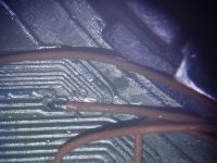
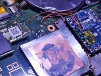
u need to heat it up long enough so it sticks to the ground apu ;-)View attachment 374518
This is my second picofly install and its now with raspberry pi pico and mosfets. The ground point on the apu was not sticking to the wire so i used the apu shield as the ground point.

Follow my post that I made about soldering in Switch LitesHi everyone,
First of all I'm sorry for my English, but I need your help, because during the installation of the picofly I had a problem, two soldering points have been jumped by moving the wires.
I wanted to ask you if you know any alternative soldering point for a Switch Lite from point D0 or if you know any technique to try to repair the points, I attach a photo so you can see in more detail.
Any help would be wonderful
Thank you very much
View attachment 374529
I figured I would document my process of how I approached soldering in the tiny and tight areas of the switch lite, along with the close proximity of the pads to each other.
The main philosophy was "if it can be masked with Kapton during soldering, DO IT. Then flux it, solder it, clean it, and cover it in UV-cure resin."
This seemed to be pretty effective, and my only issues were this being my first flex install, I had to make sure I had good contact on the caps and no bridging.
View attachment 365360
Here's my V2 flex cable secured to a piece of lumber with electrical tape and kapton to do the finer masking.
View attachment 365361
It tinned easily, and soldered easily without worrying about bridging to the side pins.
View attachment 365366
Then I cleaned it, demasked it, and covered it in resin.
View attachment 365363
Here is the Lite's 3.3v points as called out by the definitive guide. I masked off the small component nearest them with Kapton, tinned the pads...
View attachment 365364
soldered my 30awg Kynar to it...
View attachment 365365
and then also covered it in resin!
View attachment 365367
This is the GND point that has been masked off and soldered to.
View attachment 365368
Here is the RST point (I opted for a single pad since I'm using 40awg magnet wire)
View attachment 365369
Here's that RST point covered in yet more resin
View attachment 365370
Masking off and tinning the DAT0 made things much simpler
View attachment 365371
Here's CMD masked out and tinned
View attachment 365372
and here's DAT0, CMD, and CLK all soldered in and resin'd
View attachment 365362
here's the flex pre-tinned
View attachment 365373
This was one of my first attempts at soldering the flex (possibly the very first) but ultimately I got it all cleaned up and functioning properly.
So I learned that doing a switch lite is slightly more difficult than doing a full-size switch, but with the right approach it doesn't have to be impossible or terrifying.
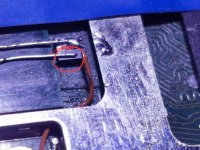
Also, fun side-note, be very careful when trying to remove the battery connector on the switch lite, because you have to disturb a jumper cable that runs the front LCD. If any of these traces are interrupted, you will have to trace which ones have lost continuity and bridge the appropriate pins with magnet wire (ask me how I know)
The short and sweet of it, is that my household now has two hacked switches (which is a 100% success rate on 100% of the consoles in the house) and I feel more confident in my micro-soldering skills


So been at it since yesterday and little good and lot of bad. Good news is, that my mosfet soldering is fine (even soldered on a 10k pull down and it glitches fast) BUT the bad news is the picofly logo is all that i can get on the screen. Pressing volume buttons gets me blue screen and putting in my SD card to get into Hekate produces a black screen!? I'm starting to think that fw2.7 (that i used intially that got me into this mess) does indeed brick the system. Currently on 2.67 and I don't know for sure but i think the emmc is gone. Can this be rectified? Anyone?@Takezo-San I know it was a long post, but I did leave a tldr
https://gbatemp.net/threads/picofly-a-hwfly-switch-modchip.622701/post-10165522
"TLDR, I fixed a BSOD by successfully restoring a backup in Hekate. Maybe the emmc somehow gets corrupted during installs? And, yes, there's actually plenty more to that story, like how mine was actually a 256gb emmc upgrade XD"

https://gbatemp.net/threads/picofly-aio-thread.628951/post-10170289So been at it since yesterday and little good and lot of bad. Good news is, that my mosfet soldering is fine (even soldered on a 10k pull down and it glitches fast) BUT the bad news is the picofly logo is all that i can get on the screen. Pressing volume buttons gets me blue screen and putting in my SD card to get into Hekate produces a black screen!? I'm starting to think that fw2.7 (that i used intially that got me into this mess) does indeed brick the system. Currently on 2.67 and I don't know for sure but i think the emmc is gone. Can this be rectified? Anyone?
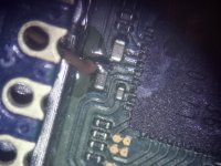
Thanks to @floxcap theres a clue about your cases.
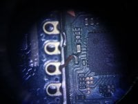
Try check your dat0 solder, i am pretty sure the reason emmc cannot initialized its because the dat0 short circuit with other dat. Theres also possibility on cmd and clk, also the resistor.

FW 2.73If you are on the new fw I guess it's saying ==* so you need to check mosfet, you might have a loose connection
I have send The images of installation.
I have attached 2 videos, first when all ok. Other video is only boot on OFW.
Attachments
-
 IMG_20230527_162715.jpg2.8 MB · Views: 42
 -
 IMG_20230527_162725.jpg2.2 MB · Views: 35
 -
 IMG_20230527_162734.jpg2.4 MB · Views: 37
 -
 IMG_20230527_181248.jpg1.9 MB · Views: 40
 -
 IMG_20230527_185922.jpg2.1 MB · Views: 33
 -
 IMG_20230527_185929.jpg2.2 MB · Views: 31
 -
 IMG_20230527_185933.jpg2.3 MB · Views: 32
 -
 IMG_20230527_185937.jpg2.4 MB · Views: 27
 -
 IMG_20230527_185949.jpg2.3 MB · Views: 26
 -
 IMG_20230527_190143.jpg2.7 MB · Views: 34
 -
 IMG_20230527_190147.jpg2.3 MB · Views: 32
 -
 IMG_20230527_190207.jpg2.7 MB · Views: 31
 -
VID_20230527_193456.mp413.9 MB
-
VID_20230528_210744.mp420.3 MB
Last edited by cicci084,
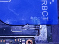
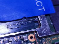
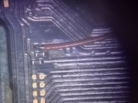
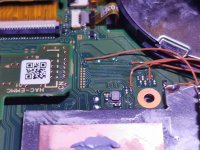
This point might have disconnectedFW 2.73
I have send The images of installation.
Also, if the wire used here is not copper, the power rating might be different so it might not support the current load
*Edit: I looked at the photos, everything else looks great
Attachments
Last edited by QuiTim,

it looks like your solder balls on top of the caps are building a bit much height wise. If they are taller than the apu core the shield will press against them which might make them snap off or come loose. Try to look from the side and compare height against apu coreWhat do you guys think?
First of all thanks for the replies.This point might have disconnected
Also, if the wire used here is not copper, the power rating might be different so it might not support the current load
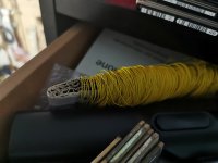
I think it's copper as tin clings very easily.
It is the self-stripping cable (photo attached) used precisely for modchip playstation 1/2.
These photos that I have inserted are from the installation, as I have already written, the console started up with the classic no sd card screen.
I started hekate and made backups successfully.
I also installed some roms, after creating Emummc.
The console has been stationary, it hasn't taken any bumps. It simply now only boots into OFW after rp2040 flashes.
I mean without shock how can a cable come off? Too much heat generated by the load/amperage?
Attachments
I actually am currently experiencing this with one of my Nephew's switch lites that I recently modded. The last few days both nephew's switch lites have been glitching and booting to CFW fine (albeit a bit slower than I might like) but they were also my first consoles to have XIAO 2040's in them. One still seems to be fine, but the other boots straight to OFW, as if there is no glitch occurring.First of all thanks for the replies.
I think it's copper as tin clings very easily.
It is the self-stripping cable (photo attached) used precisely for modchip playstation 1/2.
These photos that I have inserted are from the installation, as I have already written, the console started up with the classic no sd card screen.
I started hekate and made backups successfully.
I also installed some roms, after creating Emummc.
The console has been stationary, it hasn't taken any bumps. It simply now only boots into OFW after rp2040 flashes.
I mean without shock how can a cable come off? Too much heat generated by the load/amperage?
Both are on 2.73 firmware, and after letting it sit for a while (read as several hours) I tried turning it on and got it to glitch successfully one time. Turned it off, then back on again and it booted to OFW.
I plan to swap out the XIAO 2040 with a Waveshare 2040-tiny once it comes on Tuesday, till then, I guess the XIAO might be failing?
I would not bet on it, I mean what are the chances of Xiao failing while doing almost nothing for most of the time..I actually am currently experiencing this with one of my Nephew's switch lites that I recently modded. The last few days both nephew's switch lites have been glitching and booting to CFW fine (albeit a bit slower than I might like) but they were also my first consoles to have XIAO 2040's in them. One still seems to be fine, but the other boots straight to OFW, as if there is no glitch occurring.
Both are on 2.73 firmware, and after letting it sit for a while (read as several hours) I tried turning it on and got it to glitch successfully one time. Turned it off, then back on again and it booted to OFW.
I plan to swap out the XIAO 2040 with a Waveshare 2040-tiny once it comes on Tuesday, till then, I guess the XIAO might be failing?
Could it be that the mosfet gate isn't closing?
Does Xiao give same set of error codes (never had one so I don't know)?
At least it's not bsod
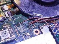
This is one of my double mosfet installs. What are the chances both gates aren't closing?I would not bet on it, I mean what are the chances of Xiao failing while doing almost nothing for most of the time..
Could it be that the mosfet gate isn't closing?
Does Xiao give same set of error codes (never had one so I don't know)?
At least it's not bsod
Similar threads
- Replies
- 3
- Views
- 751
- Replies
- 42
- Views
- 5K
- Replies
- 5
- Views
- 1K
- Replies
- 6
- Views
- 2K
- Replies
- 8
- Views
- 2K
Site & Scene News
New Hot Discussed
-
-
58K views
Nintendo Switch firmware 18.0.0 has been released
It's the first Nintendo Switch firmware update of 2024. Made available as of today is system software version 18.0.0, marking a new milestone. According to the patch... -
29K views
GitLab has taken down the Suyu Nintendo Switch emulator
Emulator takedowns continue. Not long after its first release, Suyu emulator has been removed from GitLab via a DMCA takedown. Suyu was a Nintendo Switch emulator... -
21K views
Atmosphere CFW for Switch updated to pre-release version 1.7.0, adds support for firmware 18.0.0
After a couple days of Nintendo releasing their 18.0.0 firmware update, @SciresM releases a brand new update to his Atmosphere NX custom firmware for the Nintendo...by ShadowOne333 94 -
18K views
Wii U and 3DS online services shutting down today, but Pretendo is here to save the day
Today, April 8th, 2024, at 4PM PT, marks the day in which Nintendo permanently ends support for both the 3DS and the Wii U online services, which include co-op play...by ShadowOne333 176 -
16K views
Denuvo unveils new technology "TraceMark" aimed to watermark and easily trace leaked games
Denuvo by Irdeto has unveiled at GDC (Game Developers Conference) this past March 18th their brand new anti-piracy technology named "TraceMark", specifically tailored...by ShadowOne333 101 -
15K views
GBAtemp Exclusive Introducing tempBOT AI - your new virtual GBAtemp companion and aide (April Fools)
Hello, GBAtemp members! After a prolonged absence, I am delighted to announce my return and upgraded form to you today... Introducing tempBOT AI 🤖 As the embodiment... -
12K views
Pokemon fangame hosting website "Relic Castle" taken down by The Pokemon Company
Yet another casualty goes down in the never-ending battle of copyright enforcement, and this time, it hit a big website which was the host for many fangames based and...by ShadowOne333 65 -
11K views
MisterFPGA has been updated to include an official release for its Nintendo 64 core
The highly popular and accurate FPGA hardware, MisterFGPA, has received today a brand new update with a long-awaited feature, or rather, a new core for hardcore...by ShadowOne333 51 -
11K views
Apple is being sued for antitrust violations by the Department of Justice of the US
The 2nd biggest technology company in the world, Apple, is being sued by none other than the Department of Justice of the United States, filed for antitrust...by ShadowOne333 80 -
10K views
The first retro emulator hits Apple's App Store, but you should probably avoid it
With Apple having recently updated their guidelines for the App Store, iOS users have been left to speculate on specific wording and whether retro emulators as we...
-
-
-
223 replies
Nintendo Switch firmware 18.0.0 has been released
It's the first Nintendo Switch firmware update of 2024. Made available as of today is system software version 18.0.0, marking a new milestone. According to the patch...by Chary -
176 replies
Wii U and 3DS online services shutting down today, but Pretendo is here to save the day
Today, April 8th, 2024, at 4PM PT, marks the day in which Nintendo permanently ends support for both the 3DS and the Wii U online services, which include co-op play...by ShadowOne333 -
169 replies
GBAtemp Exclusive Introducing tempBOT AI - your new virtual GBAtemp companion and aide (April Fools)
Hello, GBAtemp members! After a prolonged absence, I am delighted to announce my return and upgraded form to you today... Introducing tempBOT AI 🤖 As the embodiment...by tempBOT -
146 replies
GitLab has taken down the Suyu Nintendo Switch emulator
Emulator takedowns continue. Not long after its first release, Suyu emulator has been removed from GitLab via a DMCA takedown. Suyu was a Nintendo Switch emulator...by Chary -
101 replies
Denuvo unveils new technology "TraceMark" aimed to watermark and easily trace leaked games
Denuvo by Irdeto has unveiled at GDC (Game Developers Conference) this past March 18th their brand new anti-piracy technology named "TraceMark", specifically tailored...by ShadowOne333 -
96 replies
The first retro emulator hits Apple's App Store, but you should probably avoid it
With Apple having recently updated their guidelines for the App Store, iOS users have been left to speculate on specific wording and whether retro emulators as we...by Scarlet -
94 replies
Atmosphere CFW for Switch updated to pre-release version 1.7.0, adds support for firmware 18.0.0
After a couple days of Nintendo releasing their 18.0.0 firmware update, @SciresM releases a brand new update to his Atmosphere NX custom firmware for the Nintendo...by ShadowOne333 -
80 replies
Apple is being sued for antitrust violations by the Department of Justice of the US
The 2nd biggest technology company in the world, Apple, is being sued by none other than the Department of Justice of the United States, filed for antitrust...by ShadowOne333 -
74 replies
Delta emulator now available on the App Store for iOS
The time has finally come, and after many, many years (if not decades) of Apple users having to side load emulator apps into their iOS devices through unofficial...by ShadowOne333 -
65 replies
Pokemon fangame hosting website "Relic Castle" taken down by The Pokemon Company
Yet another casualty goes down in the never-ending battle of copyright enforcement, and this time, it hit a big website which was the host for many fangames based and...by ShadowOne333
-
Popular threads in this forum
General chit-chat
-
 Psionic Roshambo
Loading…
Psionic Roshambo
Loading…
-
-
 @
RedColoredStars:
Last thing I told her is how much I love her, and that Im not leaving her there forever and I promise to come back and take her back home with me.
@
RedColoredStars:
Last thing I told her is how much I love her, and that Im not leaving her there forever and I promise to come back and take her back home with me. -
-
-
-
-
-
-
-
-
-
-
-
-
-
-
-
-
-
-
-
-
@
RedColoredStars:
There is an actual trailer with footage too. lol. Going to watch it tonight. Grabbed it from... a place.
-
-
 @
SylverReZ:
@Psionic Roshambo, JonTron's back yet again until he disappears into the void for another 6 or so months.
@
SylverReZ:
@Psionic Roshambo, JonTron's back yet again until he disappears into the void for another 6 or so months.