I took a deep moment while reading your comment, and I remembered something that I always do when installing MOSFETs that I saw nobody does.A good tip won't help you if the iron itself is putting a high voltage out of the main body of the iron. The tip will conduct that voltage to whatever you are working on. We had to throw away a lot of our old irons at work some time ago because they were not ESD safe.
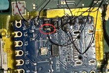
I suppose the other possibility is that you've made the same mistake on all the units with the problem? Like getting mixed up and soldering to DAT1 instead of DAT0? Triple check all the connections you've made to the pictures in the guide to make sure they are all to the correct points.
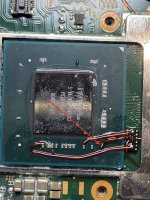
I GRIND , with a grinding pen , the ground point on the APU to put solder on it. Sometimes I'd grind a bit too much. Could this be the reason?
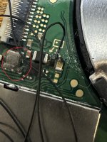
I'm talking about the point in the arrow.
@Dee87 , @deep , @rehius I'd appreciate your opinion on this.