Hacking Hardware Picofly - a HWFLY switch modchip

rehius

Well-Known Member
Member
Joined
Feb 6, 2023
Messages
377
Trophies
1
Age
34
XP
1,790
Country
Canada
I often see people saying that they have recently broken their NAND or boot0, but what is the mechanism behind this happening? It might be a good idea to compile a list of things to be aware of to prevent this from happening. What do you think?
oh, it's easy. the "toolbox unlock" breaks boot0, so please use .uf2 unlock

my fault
 

khuong

Well-Known Member
Member
Joined
Jul 18, 2018
Messages
1,542
Trophies
1
Age
44
XP
6,503
Country
Canada
Just a quick question, is everyone using microscopes to solder? Is there something cheap I can use? Seen mixed thoughts on them magnifying headband things

I wouldn't use cheap or opinions..

Good old rule, measure twice, cut once..

Get the right tools, and you won't spend the time or need to fix things afterwards.

These are tiny components, you can easily knock something, over heat, bridge, etc etc.. if you're not skilled at soldering already, it'll be difficult for novices...

You can get a cheap scope/light for soldering on amazon, aliexpress, for 30-100$.

If you wear glasses, magnifying glasses get expensive to make it fit right over glasses, or replace your glasses all together (what I have).

I use a combination of both, however I prefer the scope.. it's much easier... but again.. I wouldn't go "cheap" route.. unless you're skilled, or have spares... or don't mind forking out a lot more money to fix things than to get right equipment
 
  • Like
Reactions: Kyle46791

rskL

Member
Newcomer
Joined
Mar 21, 2023
Messages
12
Trophies
0
Age
36
XP
33
Country
United Kingdom
You need both of them, plus some additional files. There are alot of guides on how to do that (a couple of them in this thread aswell).
Just google "switch homebrew" and you will have all ypur answers because this precedure is the same whichever modchip you use.
Post automatically merged:


I Installed my first one with my camera phone and it was pain in the a**
If you plan on ever doing any smd solderin in the future get a microscope (it does not have to be high end)

Wow, great job if you managed to soder those with just a magnifying glass.
What I did was that I put the phone in recording mode with flash on ( so the screen won't shut off and the light stays on). Then suspended the phone on top of 2 soda cans and worked my way with solder in pcb. Midway through this I orderd a microscope because I was not sure I will be able to finish the work since I was knocking my phone over with the solder every 20seconds :D

I have a phone with really good macro lens so if I find a decent way of mounting it with a big led light it should be fine for this kind of thing?


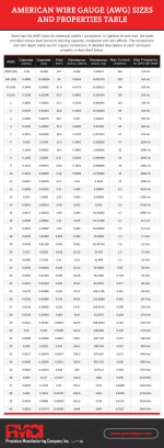
Could anyone tell me what guage of wire should be used? the enamel copper stuff isn't in normal guage size it's in mm. Also which double sided tape? Or is it all non conductive? Or should I get kapton tape ?
 
Last edited by rskL,

everyonesweird

Active Member
Newcomer
Joined
Apr 9, 2021
Messages
26
Trophies
0
Age
31
XP
122
Country
Nepal
Look, Mom, No Microscope!!!!
Will tidy up the wirings and remove the type C port after i fully test firmware v2.6. Waiting for its release..
Thanks everybody!

7e9024fc1db069ef63cd47aeda2f8bfa.jpg
845236e9b24066f3f1c5441f687f5e5f.jpg


Sent from my SM-G781B using Tapatalk
 
Last edited by everyonesweird,

QuiTim

Well-Known Member
Member
Joined
Mar 30, 2023
Messages
754
Trophies
0
XP
1,153
Country
Albania
I have a phone with really good macro lens so if I find a decent way of mounting it with a big led light it should be fine for this kind of thing?


Could anyone tell me what guage of wire should be used? the enamel copper stuff isn't in normal guage size it's in mm. Also which double sided tape? Or is it all non conductive? Or should I get kapton tape ?
My phone flashlight did a good job (just start recording with flash on and you are set).
I think it was 30awg for power and 34awg for the rest.
Here is the chart for awg to mm
 

Attachments

  • American-Wire-Gauge-AWG-Sizes-and-Properties-Table.png
    American-Wire-Gauge-AWG-Sizes-and-Properties-Table.png
    223 KB · Views: 56

khuong

Well-Known Member
Member
Joined
Jul 18, 2018
Messages
1,542
Trophies
1
Age
44
XP
6,503
Country
Canada
I have a phone with really good macro lens so if I find a decent way of mounting it with a big led light it should be fine for this kind of thing?


Could anyone tell me what guage of wire should be used? the enamel copper stuff isn't in normal guage size it's in mm. Also which double sided tape? Or is it all non conductive? Or should I get kapton tape ?

30-34 AWG.. 24-28AWG for Power/GNDs.

Kapton Tape -- heat resistant and non conductive.. (just loop it, or tape it down)

Flux.. is a must..
Solder + Low Melt Solder (for making removing things easier)
Solder Braid/Wick.. (for removing excess solder/clean up)
70-99% ISO Alch to clean..

Cheap microscope... 99$ CDN..

1680277943893.png
 

pamon15

New Member
Newbie
Joined
Mar 31, 2023
Messages
3
Trophies
0
Age
35
XP
39
Country
United Kingdom
After I flashed uf2 to zero, I reset the zero and the LED goes BLUE(3s)->PURPLE(1s)->off, is this normal? If I short the color jumper, it becomes BLUE(3s)->CYAN(1s)->off. I read from the AIO thread that the color should be red after flashing uf2?
 

rehius

Well-Known Member
Member
Joined
Feb 6, 2023
Messages
377
Trophies
1
Age
34
XP
1,790
Country
Canada
After I flashed uf2 to zero, I reset the zero and the LED goes BLUE(3s)->PURPLE(1s)->off, is this normal? If I short the color jumper, it becomes BLUE(3s)->CYAN(1s)->off. I read from the AIO thread that the color should be red after flashing uf2?
BLUE->PURPLE is a correct switch position

RED is a short blink right after you copy the .UF2 file
 

master_0123

Member
Newcomer
Joined
Dec 31, 2022
Messages
11
Trophies
0
Age
36
XP
101
Country
China
IMG_20230329_225706.jpg
IMG_20230331_184621.jpg
IMG_20230331_234051.jpg
I think firmware 2.5 is not compatible with my nand(KLMCG4JETD).The hekate always say "emmc is in slower mode"(eMMC info).And once you laod stock HOS,end with failure and the boot0 is broken .Luckily I had backuped my nand.
When I change back the tx-chip,everything works well.
Post automatically merged:

无标题.png

The left is original boot0, right is changed boot0.The right one is backuped after boot failure.
 
Last edited by master_0123,
  • Like
Reactions: Ricky_25

cowboy619

Well-Known Member
Member
Joined
Jan 22, 2014
Messages
248
Trophies
1
Age
40
Location
Cape Town, Western Cape
XP
1,810
Country
  • Like
Reactions: Ricky_25

jkyoho

Well-Known Member
Member
Joined
Sep 2, 2020
Messages
1,270
Trophies
0
Age
39
Location
TORONTO
Website
form.jotform.com
XP
2,201
Country
Canada
  • Like
Reactions: Ricky_25

rehius

Well-Known Member
Member
Joined
Feb 6, 2023
Messages
377
Trophies
1
Age
34
XP
1,790
Country
Canada
I have made a board with 47ohm resistors.View attachment 362362
such issues like you describe happen because of eMMC lines noise. for example, it could be the excess capacitance caused by your flat cable and header.

the resistors solution was made for rp2040-zero board and direct wires. it may not fit for your board. if possible, place resistors on the other end, closer to the eMMC
 

Site & Scene News

Popular threads in this forum

General chit-chat
Help Users
    SylverReZ @ SylverReZ: https://www.youtube.com/watch?v=vCadcBR95oU