It's standard practice. You also want to debounce the SD-Card by putting a .1uF decoupling capacitor on the power rail, close as possible.
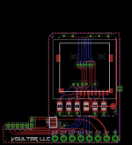
Aside from small tweaks. I'm done laying/routing this out. I've stuffed the current limiting resistors above the micro-sd port as well as the decoupling capacitor. There's a header at the very bottom that breaks out all of the signals so that you can easily read/write to the eNAND by either soldering to them or by using dupont connectors.
There's a jumper that you can short to choose between the onboard eMMC or "SD". This is useful if you want to put the stock eMMC eNAND back onto the bus.
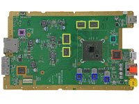
Here's a better preview to give everyone an idea of where it's going to live. I'll send off for a few copies and see how fitments works before releasing this into the wild for everyone to use.
Looks great. My only concern is that the jumper gives people the idea that they can just switch between SD and eMMC how they feel and mess up the SLC cache. Maybe it would make sense to put at least a warning on it.
Where will GND and 3V3 connect to?
What microSD slot will it use?
I think I will move my Wii U over to that as soon as it is available. Alone for adding the resistors it will be worth it. And obvoisly it's much cleaner.
I didn't have problems without the resistors yet, but I am attached to this specific console (also it's just borrowed) so I better not risk damaging the SoC I/Os.
Provided that recovery menu tool for writing back SLC/MMC dumps is made, won't it effectively _be_ possible to switch between them at will? Can SLC be so desynced from the MMC that the recovery menu won't function?
Yes, in fact I believe I got my SLC cache so de synced that it wouldn't even read from the MLC anymore. It was just going for that Multiple Block Write and then died without ever finishing the command. And at that point the recovery menu wouldn't work and there was no way without flashing the slc through hardware.
The only reason I see why you would want to do this mod is because your eMMC is dying. Once you are on SD, there is no point of going back.
The only purpose I see for that jumper is if someone wants to dump or flash the eMMC in hardware. And for that a jumper or switch would be a good and valid option.
I am just afraid of people messing up der SLC cache and then it get's nasty. Without a complete backup they will be totally lost and even with backup it could require hardware flashing of the SLC, which is very bad.
I am also looking into streamlining the process on the software side. What I imagine:
The recovery menu has an option "dump everything". It will first dump otp and seeprom, then logs and system.xml and then it would dump SLC + MLC in case anything goes wrong.
If the console isn't able to run the recovery menu anymore you would do the mlc dump through the QSB.
After that you power down your wii u. cut the trace, solder @Voultar QSB, write the MLC Image to the SD card and put the SD into the QSB.
Then you would run a "check mlc" option from the recovery menu. It will try to read every file on the mlc and generate a list of broken files.
From this list you can get the files from ~somewhere~ (Either another console or NUS), place them in a folder on the SD and run a "replace files" option in the recovery menu. It would get the files from the folder on the SD, copy them to the mlc and then move them over the original broken file.
What do you think this process?
I still have problems with the SLC dump and could really use the help from someone more familiar with IOSU. The other options are trivial to implement.
@Voultar I assume you want to release a video on this soon and maybe also include the software side? If you tell me when you need it I would see if I can get something ready for you to show the process. Also if you would be interested I would offer you to proofread your script to make sure it lines up with what we have learned so far (but I think by now you already have a good picture).
Possibly. The backup probably isn't of much use (maybe the otp.bin can become usefull). But if you are lucky the the eMMC didn't die completely but only switched read only (which is likely), then you can still dump it through hardware and write it to an SD. Maybe that is enough to get your Wii U booting again. If it crashes later in the boot process, it is probably fixable through udpih. If not even udpih is working we could use your otp and try to inject fresh copies of broken files with wfs-inject. But wfs-inject should be only the last resort, as it bypasses the SLC cache.
EDIT: Also I got finally another Wii U, that is actually broken. @V10lator also now has a Wii U with probably bad eMMC. So we test the process there.
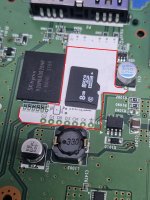
Sorry to be the bearer of bad news, but I believe that capacitor is populated on some early Wii U consoles, although its actual designation is C655 (C617 is the designation for the much smaller capacitor next to it)
Would it be worth considering making it a flex PCB? so that the microSD card slot could sit directly over the original eMMC chip?
Or how feasible would it be to solder to the vias on the back of the motherboard, instead of directly to the resistors? (I dont know if they are tented vias?)
I would rather not have to remove a component, even if its not absolutely required.
My early Wii U (bought 2 days after launch also doesn't have C655) so I think Voultar is right there. Sadly this cap is on a 5V rail or else you would probably have gotten the 3V3 from there I assume.
In the worst case one could just remove the cap if someone has it.
@SDIO - When you're manually reading in the eNAND, does your Wii-U in standby mode supply voltage to the eNAND so that you don't have to provide a voltage source when dumping/writing?
Yes during both the SLC and the MLC readouts/writes the Wii U provides the power. I even powerd the raspberry I used for that from the Wii Us USB ports. That's also how it was recommended in the original hardmod dump Thread.
If the clk line is cut, the IOSU wont find the MLC and will give up and crash and hang, so it shouldn't interfere.
EDIT: sorry I didn't read correctly (it's late here). No the Wii U doesn't provide power in Standby. You have to turn it on to power the eMMC.
EDIT2: and I assume with Standby you mean red light. There is also this other mode where the LED is yellow, but that shouldn't work without the eMMC anyway.
OK, I'm trying to accommodate for every Wii-U revision that I don't know about, while making sure that the top RF shield can fit snuggly down and be put back together.
I've rerouted and reshaped this a little more. The castellated edges on the left grab the 4-bit data IO, clock, and command.
3V3 is the only wire, and it solders to Q6 (top left). The leg on the right with the castellated edge grabs a rigid ground from the electrolytic cap C13.
The breakout at the bottom is still there so one could easily I stall a header to read/dump the MLC, which I see as being critical to this design. The solder jumper must be handled with care. But I chose to make this a solder strap and NOT a switch because as SDSIO said, this shouldn't be messed with.
Would it not be possible to make the PCB a little shorter to clear U29 entirely? For example (And please forgive my terrible photo editing skills)
<EDIT> If the issue is clearance for inserting/removing the microSD card, would it fit better if the slot was rotated 180degrees? Something closer to the attached mockup, although obviously the traces would need rerouting,
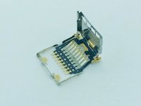
Or alternatively there are 'flip top' micro SD slots which wouldn't require the extra space for insertion/removal.
It's the first Nintendo Switch firmware update of 2024. Made available as of today is system software version 18.0.0, marking a new milestone. According to the patch...
Emulator takedowns continue. Not long after its first release, Suyu emulator has been removed from GitLab via a DMCA takedown. Suyu was a Nintendo Switch emulator...
After a couple days of Nintendo releasing their 18.0.0 firmware update, @SciresM releases a brand new update to his Atmosphere NX custom firmware for the Nintendo...
Today, April 8th, 2024, at 4PM PT, marks the day in which Nintendo permanently ends support for both the 3DS and the Wii U online services, which include co-op play...
Hello, GBAtemp members! After a prolonged absence, I am delighted to announce my return and upgraded form to you today...
Introducing tempBOT AI 🤖
As the embodiment...
Yet another casualty goes down in the never-ending battle of copyright enforcement, and this time, it hit a big website which was the host for many fangames based and...
The highly popular and accurate FPGA hardware, MisterFGPA, has received today a brand new update with a long-awaited feature, or rather, a new core for hardcore...
The 2nd biggest technology company in the world, Apple, is being sued by none other than the Department of Justice of the United States, filed for antitrust...
With Apple having recently updated their guidelines for the App Store, iOS users have been left to speculate on specific wording and whether retro emulators as we...
The romhacking community is always a source for new ways to play retro games, from completely new levels or stages, characters, quality of life improvements, to flat...
It's the first Nintendo Switch firmware update of 2024. Made available as of today is system software version 18.0.0, marking a new milestone. According to the patch...
Today, April 8th, 2024, at 4PM PT, marks the day in which Nintendo permanently ends support for both the 3DS and the Wii U online services, which include co-op play...
Hello, GBAtemp members! After a prolonged absence, I am delighted to announce my return and upgraded form to you today...
Introducing tempBOT AI 🤖
As the embodiment...
Emulator takedowns continue. Not long after its first release, Suyu emulator has been removed from GitLab via a DMCA takedown. Suyu was a Nintendo Switch emulator...
With Apple having recently updated their guidelines for the App Store, iOS users have been left to speculate on specific wording and whether retro emulators as we...
After a couple days of Nintendo releasing their 18.0.0 firmware update, @SciresM releases a brand new update to his Atmosphere NX custom firmware for the Nintendo...
The 2nd biggest technology company in the world, Apple, is being sued by none other than the Department of Justice of the United States, filed for antitrust...
The time has finally come, and after many, many years (if not decades) of Apple users having to side load emulator apps into their iOS devices through unofficial...
Yet another casualty goes down in the never-ending battle of copyright enforcement, and this time, it hit a big website which was the host for many fangames based and...
Nintendo has recently announced through their social media accounts that a new Indie World stream will be airing tomorrow, scheduled for April 17th, 2024 at 7 a.m. PT...