


And also less resistance on the way by having it closer since people might use shitty wire.Time to debunk this once and for all. The original flex cable has quite a distance from the capacitors. Its more of a design choice that has been used since SX. No reason the mosfet incorporated in the main chip will work differently.
The only reason the "close to the APU" is a thing is because of the beta people trying out stuff to make their lives easier by soldering it directly to the capacitor.
You are using an out of date browser. It may not display this or other websites correctly.
You should upgrade or use an alternative browser.
You should upgrade or use an alternative browser.

An option to solder it on the borad would be great. Will make installs much cleanerAnd also less resistance on the way by having it closer since people might use shitty wire.

And also less resistance on the way by having it closer since people might use shitty wire.
I doubt wire size will impact it. Its not like its going far, the main chip is placed right beside the apu anyway. Its not that far as you think.


ok, thanks for the explaining, so the eddy currents, have no effect at all? nor the timings?Time to debunk this once and for all. The original flex cable has quite a distance from the capacitors. Its more of a design choice that has been used since SX. No reason the mosfet incorporated in the main chip will work differently.
The only reason the "close to the APU" is a thing is because of the beta people trying out stuff to make their lives easier by soldering it directly to the capacitor.

It will increase resistance and inductance. Keep in mind the mosfet is shorting this voltage rail for a moment which means there will be many amps flowing with the capacitors still in place. And the inductance will cause ringing which has the potential to destroy your SoC if it goes out of hand.Time to debunk this once and for all. The original flex cable has quite a distance from the capacitors. Its more of a design choice that has been used since SX. No reason the mosfet incorporated in the main chip will work differently.
The only reason the "close to the APU" is a thing is because of the beta people trying out stuff to make their lives easier by soldering it directly to the capacitor.
If the PCB would be sitting between RAM and SoC it's probably fine but the extra wire length when it's not can be problematic.

Did I not mention the flex cable that everyone is using right now and ever since sx days is quite far apart from the capacitor.It will increase resistance and inductance. Keep in mind the mosfet is shorting this voltage rail for a moment which means there will be many amps flowing with the capacitors still in place. And the inductance will cause ringing which has the potential to destroy your SoC if it goes out of hand.
If the PCB would be sitting between RAM and SoC it's probably fine but the extra wire length when it's not can be problematic.

Well, not so simple. The FETs responsible for performing the glitch on the APU could reach currents up to 10A. The via's on the CPU flex are thick enough to support this.Time to debunk this once and for all. The original flex cable has quite a distance from the capacitors. Its more of a design choice that has been used since SX. No reason the mosfet incorporated in the main chip will work differently.
The only reason the "close to the APU" is a thing is because of the beta people trying out stuff to make their lives easier by soldering it directly to the capacitor.
If the FET would be moved to the chip PCB, thicker wires would be needed for the install, nontheless there's a high probability for signal delay by using longer wires, so not sure if the glitch would work properly.

I'm currently working on a SwitchME port to the adafruit tinyusb library, which opens up a massive array of microcontrollers including the RP2040 to supporting RCM injection, does anyone have any experience with low level calls to the TinyUSB library as it's shockingly poorly documented?
The wires needed to handle the current wouldn't be able to fit through the RF shielding without cutting, the flex cable doesn't move them that far away in the grand scheme of things, as you've said putting the module inside the shield will probably be alright but the mcfly wont fit inside the shield and i dont want to be held responsible for people using magnet wire for the main glitch signal, it turning into a fuse and them causing damage. It's easier to just use the hwfly flex or one of the other flexes people are working onTime to debunk this once and for all. The original flex cable has quite a distance from the capacitors. Its more of a design choice that has been used since SX. No reason the mosfet incorporated in the main chip will work differently.
The only reason the "close to the APU" is a thing is because of the beta people trying out stuff to make their lives easier by soldering it directly to the capacitor.
I'm currently working on a SwitchME port to the adafruit tinyusb library, which opens up a massive array of microcontrollers including the RP2040 to supporting RCM injection, does anyone have any experience with low level calls to the TinyUSB library as it's shockingly poorly documented?
The wires needed to handle the current wouldn't be able to fit through the RF shielding without cutting, the flex cable doesn't move them that far away in the grand scheme of things, as you've said putting the module inside the shield will probably be alright but the mcfly wont fit inside the shield and i dont want to be held responsible for people using magnet wire for the main glitch signal, it turning into a fuse and them causing damage. It's easier to just use the hwfly flex or one of the other flexes people are working on
Since you're making a new chip, might as well not use the flex cable that they can and will monopolize. Its the logical approach tbh. Not to mention, the flex cable is not that accessible to everyone with its only source, aliexpress.
If you're opposed to magnet wire, you could use ribbon cable laser for ps2 which can be cut in half and bridging the 2 halfs for both capacitors.
That's just 1 of the possibilities. Flex cable can be designed and purchased without the mosfets in built from pcbway too. You wouldn't want people to solder mosfets to flex cable, high risk procedure.
There are alternative open source flexes ive seen in development. I'm not opposed to magnet wire as a concept and indeed it will be very useful for soldering the EMMC lines however for the currents that it will conduct during the glitching it is not of sufficient gauge. my board also supports direct soldered FETs so it is not dependent on aliexpress hwfly cablesSince you're making a new chip, might as well not use the flex cable that they can and will monopolize. Its the logical approach tbh. Not to mention, the flex cable is not that accessible to everyone with its only source, aliexpress.
If you're opposed to magnet wire, you could use ribbon cable laser for ps2 which can be cut in half and bridging the 2 halfs for both capacitors.
That's just 1 of the possibilities. Flex cable can be designed and purchased without the mosfets in built from pcbway too. You wouldn't want people to solder mosfets to flex cable, high risk procedure.
The Mcfly will be open source, so once it's complete as is you could add the mosfet and test it yourself. I'm deliberately embarking on a conservative design to guarantee success
Yeah, that flexex have Thick wires, and really are not so "appart" from caps, are at the very edge of the CPU, the flexes also have a design for avoid eddy currents because have the GND wires along the path.Did I not mention the flex cable that everyone is using right now and ever since sx days is quite far apart from the capacitor.
Quick update: still waiting for components unfortunately, LCSC are being frustrating. I'm working on other fun things in the background i'm hoping to announce soon
No it's not, there's a reason it wasn't included on the chip.Did I not mention the flex cable that everyone is using right now and ever since sx days is quite far apart from the capacitor.
")
At this time "far" is a maleable concept. you need to have it as close as you can to the capacitors, is like the capacitors they must be close as can to the CPU.No it's not, there's a reason it wasn't included on the chip.
The ideal point is exactly by the cap, but that is for the skilled ones. the flex cable was designed to be easy of install and still be closest to caps.
Put the mosfet outside of the CPU enclosure will not work at all. search about eddy currents and clock timings.
Yea this is incorrect, again. It will work outside the cpu enclosure. People tend to exaggerate the distance of the mosfets thinking its so far that it will get loss signals.Put the mosfet outside of the CPU enclosure will not work at all. search about eddy currents and clock timings.
Mcfly/RP2040 is right next to the SX flex cable original position.
Out of interest have you actually tested this to demonstrate that it properly works?Yea this is incorrect, again. It will work outside the cpu enclosure. People tend to exaggerate the distance of the mosfets thinking its so far that it will get loss signals.
Mcfly/RP2040 is right next to the SX flex cable original position.
Post automatically merged:
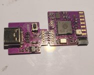
I sacrificed another rp2040 project for this but here it is, at functionally assembled (no FFC connector) a total thickness of 1.5mm on the dot at the thickest part! I'm very happy with that.
Next step is testing, see if it takes firmware and works n all that. I also need to get my extra components and build up the rest of these to send out to testers
Attachments
Last edited by Saliciae,

Board is now fully assembled, added the ffc connector. Had to change the RGB led on this one so it's not as thin as it could be but that will get sorted in the next revision, as a bonus the sk6805-e-j led I plan to use will allow me to make it even smaller!. Gonna build some more and start shipping them out.
Thanks to all who messaged me offering to test, I'll start messaging a few of you about where to send them.
This project has progressed super quickly and I'm excited to see how it performs!
Thanks to all who messaged me offering to test, I'll start messaging a few of you about where to send them.
This project has progressed super quickly and I'm excited to see how it performs!
Attachments
Similar threads
- Replies
- 3K
- Views
- 515K
- Replies
- 14
- Views
- 6K
- Replies
- 3
- Views
- 4K
- Replies
- 21
- Views
- 12K
- Replies
- 0
- Views
- 2K
Site & Scene News
New Hot Discussed
-
-
63K views
Nintendo Switch firmware 18.0.0 has been released
It's the first Nintendo Switch firmware update of 2024. Made available as of today is system software version 18.0.0, marking a new milestone. According to the patch... -
25K views
Atmosphere CFW for Switch updated to pre-release version 1.7.0, adds support for firmware 18.0.0
After a couple days of Nintendo releasing their 18.0.0 firmware update, @SciresM releases a brand new update to his Atmosphere NX custom firmware for the Nintendo...by ShadowOne333 107 -
21K views
Wii U and 3DS online services shutting down today, but Pretendo is here to save the day
Today, April 8th, 2024, at 4PM PT, marks the day in which Nintendo permanently ends support for both the 3DS and the Wii U online services, which include co-op play...by ShadowOne333 179 -
16K views
GBAtemp Exclusive Introducing tempBOT AI - your new virtual GBAtemp companion and aide (April Fools)
Hello, GBAtemp members! After a prolonged absence, I am delighted to announce my return and upgraded form to you today... Introducing tempBOT AI 🤖 As the embodiment... -
13K views
The first retro emulator hits Apple's App Store, but you should probably avoid it
With Apple having recently updated their guidelines for the App Store, iOS users have been left to speculate on specific wording and whether retro emulators as we... -
13K views
Pokemon fangame hosting website "Relic Castle" taken down by The Pokemon Company
Yet another casualty goes down in the never-ending battle of copyright enforcement, and this time, it hit a big website which was the host for many fangames based and...by ShadowOne333 66 -
13K views
MisterFPGA has been updated to include an official release for its Nintendo 64 core
The highly popular and accurate FPGA hardware, MisterFGPA, has received today a brand new update with a long-awaited feature, or rather, a new core for hardcore...by ShadowOne333 54 -
12K views
Delta emulator now available on the App Store for iOS
The time has finally come, and after many, many years (if not decades) of Apple users having to side load emulator apps into their iOS devices through unofficial...by ShadowOne333 96 -
10K views
"TMNT: The Hyperstone Heist" for the SEGA Genesis / Mega Drive gets a brand new DX romhack with new features
The romhacking community is always a source for new ways to play retro games, from completely new levels or stages, characters, quality of life improvements, to flat...by ShadowOne333 36 -
10K views
Anbernic announces RG35XX 2024 Edition retro handheld
Retro handheld manufacturer Anbernic is releasing a refreshed model of its RG35XX handheld line. This new model, named RG35XX 2024 Edition, features the same...
-
-
-
225 replies
Nintendo Switch firmware 18.0.0 has been released
It's the first Nintendo Switch firmware update of 2024. Made available as of today is system software version 18.0.0, marking a new milestone. According to the patch...by Chary -
179 replies
Wii U and 3DS online services shutting down today, but Pretendo is here to save the day
Today, April 8th, 2024, at 4PM PT, marks the day in which Nintendo permanently ends support for both the 3DS and the Wii U online services, which include co-op play...by ShadowOne333 -
169 replies
GBAtemp Exclusive Introducing tempBOT AI - your new virtual GBAtemp companion and aide (April Fools)
Hello, GBAtemp members! After a prolonged absence, I am delighted to announce my return and upgraded form to you today... Introducing tempBOT AI 🤖 As the embodiment...by tempBOT -
107 replies
Atmosphere CFW for Switch updated to pre-release version 1.7.0, adds support for firmware 18.0.0
After a couple days of Nintendo releasing their 18.0.0 firmware update, @SciresM releases a brand new update to his Atmosphere NX custom firmware for the Nintendo...by ShadowOne333 -
97 replies
The first retro emulator hits Apple's App Store, but you should probably avoid it
With Apple having recently updated their guidelines for the App Store, iOS users have been left to speculate on specific wording and whether retro emulators as we...by Scarlet -
96 replies
Delta emulator now available on the App Store for iOS
The time has finally come, and after many, many years (if not decades) of Apple users having to side load emulator apps into their iOS devices through unofficial...by ShadowOne333 -
77 replies
Nintendo takes down Gmod content from Steam's Workshop
Nintendo might just as well be a law firm more than a videogame company at this point in time, since they have yet again issued their now almost trademarked usual...by ShadowOne333 -
73 replies
Nintendo Switch firmware update 18.0.1 has been released
A new Nintendo Switch firmware update is here. System software version 18.0.1 has been released. This update offers the typical stability features as all other...by Chary -
66 replies
Pokemon fangame hosting website "Relic Castle" taken down by The Pokemon Company
Yet another casualty goes down in the never-ending battle of copyright enforcement, and this time, it hit a big website which was the host for many fangames based and...by ShadowOne333 -
54 replies
MisterFPGA has been updated to include an official release for its Nintendo 64 core
The highly popular and accurate FPGA hardware, MisterFGPA, has received today a brand new update with a long-awaited feature, or rather, a new core for hardcore...by ShadowOne333
-
Popular threads in this forum
General chit-chat
-
S
salazarcosplay
Loading…
-
 K3Nv2
Loading…
K3Nv2
Loading… -
 AncientBoi
Loading…
AncientBoi
Loading…
-
-
 @
Sicklyboy:
@Xdqwerty, to answer your question, they're a fusion Brit-pop/J-pop/electronic band with a woman vocalist. Flamingo is hands down their best known song but they've got a ton of other really good songs+1
@
Sicklyboy:
@Xdqwerty, to answer your question, they're a fusion Brit-pop/J-pop/electronic band with a woman vocalist. Flamingo is hands down their best known song but they've got a ton of other really good songs+1 -
@
Sicklyboy:
For example, one of my other favorite songs from them, with some massive house music influence -+1
-
-
-
-
-
-
-
-
-
-
-
-
-
-
-
-
-
-
-
-
-
-