Guys I need some help !!!
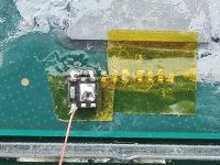
I tried to solder the mosfet but it keeps burning. I‘ve burnt 4 mosfet already.
But my switch lite is totally OK and working normally after I removed RP2040.
What could be the reason ? Has this happen to anyone else ?
Soldering Iron you are using?


 Maybe it's wrong ?