Hacking Hardware Picofly - a HWFLY switch modchip

rehius

Well-Known Member
Member
Joined
Feb 6, 2023
Messages
377
Trophies
1
Age
33
XP
1,779
Country
Canada
Rats! Aight... any safer place for drilling? xD
there are only two possible places, the one with an arrow on the PCB, and the one close to the CPU cover (requires desoldering part of the cover)

in both cases it is very easy to cut the trace in the process, so reballing is your choice, unfortunately
 

linuxares

The inadequate, autocratic beast!
Global Moderator
Joined
Aug 5, 2007
Messages
13,276
Trophies
2
XP
18,088
Country
Sweden
there are only two possible places, the one with an arrow on the PCB, and the one close to the CPU cover (requires desoldering part of the cover)

in both cases it is very easy to cut the trace in the process, so reballing is your choice, unfortunately
I hope someone develops a better "ankor" then. What I read it seems to be kind of hit and miss.
 

impeeza

¡Kabito!
Member
Joined
Apr 5, 2011
Messages
6,314
Trophies
3
Age
46
Location
At my chair.
XP
18,555
Country
Colombia
there are only two possible places, the one with an arrow on the PCB, and the one close to the CPU cover (requires desoldering part of the cover)

in both cases it is very easy to cut the trace in the process, so reballing is your choice, unfortunately
this time big N think well about that.
 

Warbeast

Active Member
Newcomer
Joined
Dec 30, 2015
Messages
40
Trophies
0
Age
43
XP
284
Country
Is this correct? Trace 6, 7 and 11 from left to right?
Looks ok to me i tested another pico with a usbc to micro adapter and couldnt get it to detect so thought maybe it uses the cc pin however it turned out just to be my old cables

also on your photo one of the boot button pads is lifted im not sure what out of the four need to be bridged
Screenshot_20230323_164316_Gallery.jpg
 

handsom_tomato

Active Member
Newcomer
Joined
Jan 24, 2023
Messages
43
Trophies
0
Age
20
XP
444
Country
Japan
Help me!
mariko v2

I tried to solder to the RST point of the eMMC, but it was too small and in the process, the land was removed. How can I connect to the RST now? Should I jumper to the left connector?
 

SQc04

Well-Known Member
Newcomer
Joined
Mar 23, 2023
Messages
99
Trophies
0
Age
21
XP
419
Country
China
Looks ok to me i tested another pico with a usbc to micro adapter and couldnt get it to detect so thought maybe it uses the cc pin however it turned out just to be my old cables

also on your photo one of the boot button pads is lifted im not sure what out of the four need to be bridged View attachment 360903
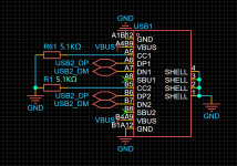
Each of the cc pins of the 16-pin Typec interface is connected to a 5.1KΩ pull-down resistor
 

Attachments

  • ){RSS3M(IL)%J)SKP4}5)IY.png
    ){RSS3M(IL)%J)SKP4}5)IY.png
    199.9 KB · Views: 44
  • Love
Reactions: impeeza

impeeza

¡Kabito!
Member
Joined
Apr 5, 2011
Messages
6,314
Trophies
3
Age
46
Location
At my chair.
XP
18,555
Country
Colombia
This is the great of temp, we have tempers from around the world, and sometimes this happen, by example recently I put a post about a condenser (which is a wright term) but on USA is more often used capacitor and the thread get confused, I am sorry for causing it.

I think land refers to the pad or the via (track) get lifted.

Normally you need to track the via and find another test point.
 
  • Like
Reactions: handsom_tomato

handsom_tomato

Active Member
Newcomer
Joined
Jan 24, 2023
Messages
43
Trophies
0
Age
20
XP
444
Country
Japan
This is the great of temp, we have tempers from around the world, and sometimes this happen, by example recently I put a post about a condenser (which is a wright term) but on USA is more often used capacitor and the thread get confused, I am sorry for causing it.

I think land refers to the pad or the via (track) get lifted.

Normally you need to track the via and find another test point.
IMG_E4159.JPG

soldering still feels too difficult for me...
 

SQc04

Well-Known Member
Newcomer
Joined
Mar 23, 2023
Messages
99
Trophies
0
Age
21
XP
419
Country
China
Anyone got a modchip on a OLED installed and a multimeter (and possibily the courage to do some scratching of soldermask?).

RED = DAT0, the image moves so I think it's the 2nd bottom.
GREEN = possible area it leads to.
BLUE, PURPLE, PINK = Areas that needs to be probed. Since they seem to go to the CPU after their transistor.
View attachment 360890View attachment 360891
View attachment 360892
It's still too risky, take the EMMC off and add an FPC between the PCB of EMMC and NS may be better
C9%A2NR)AU][ARG~_QZ782Q.png
 

impeeza

¡Kabito!
Member
Joined
Apr 5, 2011
Messages
6,314
Trophies
3
Age
46
Location
At my chair.
XP
18,555
Country
Colombia
It's still too risky, take the EMMC off and add an FPC between the PCB of EMMC and NS may be better
View attachment 360914
Yes there are boards on the market of two types one the described on that picture, you desolder the EMMC chip and reball the PCB between the EMMC chip and the console PCB, are other type where you insert a flex adapter by the side and a little tab makes contact to the actual ball of the DAT0. booth are the current options.
 
  • Like
Reactions: SQc04

Kid4life79

Member
Newcomer
Joined
Mar 23, 2023
Messages
8
Trophies
0
Age
44
XP
37
Country
United States
Looks ok to me i tested another pico with a usbc to micro adapter and couldnt get it to detect so thought maybe it uses the cc pin however it turned out just to be my old cables

also on your photo one of the boot button pads is lifted im not sure what out of the four need to be bridged View attachment 360903
Thank you for the confirmation. Yes, I was aware of the lifted pad but knew I could use 2 of the remaining 3.
 
  • Like
Reactions: impeeza

SQc04

Well-Known Member
Newcomer
Joined
Mar 23, 2023
Messages
99
Trophies
0
Age
21
XP
419
Country
China
There is a guide to repair sysnand damaged by SXOS recreating BOOT0/BOOT1 from scratch, I really do not remember the URL but you can find easily on the search at top of page.


Wow is an absolute mindblow gadget, there is there a RGB LED?


Is a good idea but for the glitch be stable you need to have the MOSFET closes as you can to the capacitors for avoid "Eddy-currents" and timing issues. That´s why even the hflw have a separated flex cable to the CPU.
Yes, the 2812B RGB LED in the 1204 package is integrated
 
  • Love
Reactions: impeeza

SQc04

Well-Known Member
Newcomer
Joined
Mar 23, 2023
Messages
99
Trophies
0
Age
21
XP
419
Country
China
Ye, but won't it get to "high" up if so? Plus extra amount of failure points because of all the ball joints.
At least better than drilling a big hole in the PCB :P
Post automatically merged:

At least better than drilling a big hole in the PCB :P
If the wire is accidentally broken during drilling, the entire PCB is scrapped, and the failure of the solder ball connection can be removed and reinstalled.
Post automatically merged:


There are no test points added to the PCB, which is very uncomfortable
 
Last edited by SQc04,
  • Haha
Reactions: impeeza

Site & Scene News

Popular threads in this forum

General chit-chat
Help Users
  • No one is chatting at the moment.
    Psionic Roshambo @ Psionic Roshambo: https://m.youtube.com/watch?v=lDRjqI-fBVI&pp=ygUPVml0Z2luIG1hZ2ljaWFu