Hacking Hardware Picofly - a HWFLY switch modchip

binkinator

Garfield’s Fitness Coach
Member
GBAtemp Patron
Joined
Mar 29, 2021
Messages
6,511
Trophies
2
XP
6,155
Country
United States

RexSonic

Well-Known Member
Newcomer
Joined
Dec 12, 2022
Messages
63
Trophies
0
XP
190
Country
Germany

Piorjade

Well-Known Member
Member
Joined
Nov 8, 2015
Messages
142
Trophies
0
XP
407
Country
Gambia, The
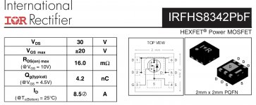
just flashed it and it is doing something...then failing, i dont have a IRFHS8342 installed in this currently, and would have to order one to actually test. i dont know if its worth doing at the minute.

You need some kind of MOSFET, otherwise it won't make sense. As @Mansi has already said, you may be even able to use the cpu flat cable of the HWFLY/SXCore.
Post automatically merged:

What do you need that specific chip for ?
It's a MOSFET (basically an electrical switch)
 

binkinator

Garfield’s Fitness Coach
Member
GBAtemp Patron
Joined
Mar 29, 2021
Messages
6,511
Trophies
2
XP
6,155
Country
United States
What do you need that specific chip for ?
Check the picture. It’s mosfet. Connecting Sink (4) and Drain (5) but controlled with a Gate (3) from the Pico. That way Pico doesn’t have to supply voltage…it’s using system voltage to do the work. Somebody smarter than me correct if I’m wrong.
BC086644-B3AC-4638-9567-941D830421B2.jpeg
 

Piorjade

Well-Known Member
Member
Joined
Nov 8, 2015
Messages
142
Trophies
0
XP
407
Country
Gambia, The
Can anyone decompile the UF2?
Post automatically merged:

Also, I'm wondering why this chip apparently only needs one MOSFET, AFAIK HWFLY and SXCore use two?
This is what I was asking before, one MOSFET controls voltage to the BPMP, but what does the other one control?
 
  • Like
Reactions: impeeza

Tafty

Well-Known Member
Member
Joined
Sep 23, 2016
Messages
116
Trophies
0
Age
36
XP
923
Country
OK so I'm allready using the cpu flex for this lite I have a pico installed on.

The only thing that is different from my original install is I don't have chip reset wired up to anything. Any ideas where these need to go
 

Piorjade

Well-Known Member
Member
Joined
Nov 8, 2015
Messages
142
Trophies
0
XP
407
Country
Gambia, The

Piorjade

Well-Known Member
Member
Joined
Nov 8, 2015
Messages
142
Trophies
0
XP
407
Country
Gambia, The
thats RST i allready have that in the correction location, im talking about on the other side there is 2 for chip reset that arent on the original wiring diagram
Woops sorry, actually I have no clue why that's there :unsure:
Post automatically merged:

Also, are these things supposed to be resistors (470 ohm?) ?
1675698278342.png
 
  • Like
Reactions: impeeza

impeeza

¡Kabito!
Member
Joined
Apr 5, 2011
Messages
6,355
Trophies
3
Age
46
Location
At my chair.
XP
18,690
Country
Colombia

Site & Scene News

Popular threads in this forum

General chit-chat
Help Users
    Xdqwerty @ Xdqwerty: