HWFLY OLED install. I can't get the DAT0 connector to connect.

HelloShitty

Well-Known Member
Member
Joined
Jan 16, 2022
Messages
252
Trophies
0
Age
124
XP
397
Country
Iran
Make sure to add solder mask on the left and right sides of it. I find that 1 joint is too flimsy.

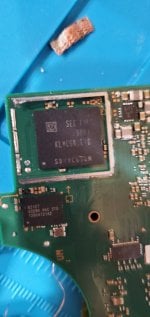
Also, not many people know this but add solder mask on the solder joints as well. If your solder is a little bit too much, it could touch the nand shield and shorting DAT0 pin to ground. Better yet, add kapton take on the insides of the nand shield.

I might had similar problem but not due to excess of solder. I think my problem could be because I soldered the enamel wire in the wrong direction, and then, to route the wire to the correct direction I had to bend it a bit inside the NAND frame! An maybe the wire did unbend itself a bit and touched the NAND frame. Then, I had to disassemble the console again, and make sure that the wire wouldn't touch the frame again (in case that was the problem) and also reflowed the anchor point and tried to give the adapter a tighter push underneath the NAND chip to ensure better contact with DAT0 line.

After that, things have been running smoothly!
 

HelloShitty

Well-Known Member
Member
Joined
Jan 16, 2022
Messages
252
Trophies
0
Age
124
XP
397
Country
Iran
I didn't use solder mask, but I used some resin from my resin 3d printer and cured it with a UV light. No idea, but figured it was about the same thing. I put it on both sides of the DAT0 pad, and put a dab near the contact point you scratch off on the board as well. Put it near the connection, but not over top; in case I needed to go back and resolder at a later date.

Thought about using super glue, but read if heated (assuming in liquid form) it can produce some nasty gasses. I know with brake cleaner that's chlorinated, a drop of that stuff vaporized can cause permanent lung damage. Decided resin was safer. lol
I used solder mask in almost every point of the PCB (but not on the mod chip). It made me feel a bit more comfortable regarding the wires to have less freedom to wiggle around and eventually get lose of the solder joints. I know that if the joints are properly done, this won't happen, but it can't hurt adding a bit of solder mask!
 
  • Like
Reactions: gangan

gangan

Member
OP
Newcomer
Joined
Mar 13, 2022
Messages
22
Trophies
0
Age
32
Location
usa
XP
76
Country
United States
I might had similar problem but not due to excess of solder. I think my problem could be because I soldered the enamel wire in the wrong direction, and then, to route the wire to the correct direction I had to bend it a bit inside the NAND frame! An maybe the wire did unbend itself a bit and touched the NAND frame. Then, I had to disassemble the console again, and make sure that the wire wouldn't touch the frame again (in case that was the problem) and also reflowed the anchor point and tried to give the adapter a tighter push underneath the NAND chip to ensure better contact with DAT0 line.

After that, things have been running smoothly!

Yeah. I could see it putting a lot of stress on solid wire if you did it backwards, bent it, then ran it the opposite direction.

I think I’ll line the inside of the shield with kapton like the other user mentioned; next time I take it apart anyway. Shouldn’t hurt anything and could prevent some boo boos. But it seemed to be a real solid connection and the resin I put on both sides should keep the pad from moving at all. It flowed around a few components, so that should keep it locked in place.


Sent from my iPhone using Tapatalk Pro
 

HelloShitty

Well-Known Member
Member
Joined
Jan 16, 2022
Messages
252
Trophies
0
Age
124
XP
397
Country
Iran
Yeah. I could see it putting a lot of stress on solid wire if you did it backwards, bent it, then ran it the opposite direction.

I think I’ll line the inside of the shield with kapton like the other user mentioned; next time I take it apart anyway. Shouldn’t hurt anything and could prevent some boo boos. But it seemed to be a real solid connection and the resin I put on both sides should keep the pad from moving at all. It flowed around a few components, so that should keep it locked in place.


Sent from my iPhone using Tapatalk Pro

Yeah, in my case it was the inexperience. I didn't think what the direction the wire should take when I soldered it. And it happened again with the GND point but in latter, as it has more space around it, it wasn't that critical.

Other than that, I think I did a reasonable job for the first time.
 

Peeta01

Active Member
Newcomer
Joined
May 3, 2007
Messages
30
Trophies
1
XP
295
Country
United States
Sorry to bring this back alive. Need some help. I keep getting .89-.90 v. Im using the dat0 adapter black corner one. Im not using the heat gun to pernamently place it, just positioning. I can seem to get .45 to .85 range from sthetix. I plug up everything getting splid red light after flashing blue.

Thanks!
 

randy_w

Well-Known Member
Member
Joined
Feb 27, 2021
Messages
709
Trophies
0
Age
34
XP
1,373
Country
United States
I keep getting .89-.90 v
That might be normal depending on your emmc manufacturer. On samsung emmc I always get 0.6-0.7V but on sk hynix emmc it's usually higher at around 0.8V. Haven't seen toshiba emmc yet so don't know their value. Anyway, it's easy to verify other solder points (like A, B, D, sp1 and sp2). If all other points' values are correct and the chip still can't train, then it's dat0's problem.
splid red light after flashing blue
Are you sure it's flashing blue? What chip are you using? Flashing blue means the chip is in usb mode on hwfly clones. If it's original sx core/lite then it means it's trying to glitch the soc, in that case you should update it to latest version of spacecraft since you are using it on an oled.
 

Peeta01

Active Member
Newcomer
Joined
May 3, 2007
Messages
30
Trophies
1
XP
295
Country
United States
That might be normal depending on your emmc manufacturer. On samsung emmc I always get 0.6-0.7V but on sk hynix emmc it's usually higher at around 0.8V. Haven't seen toshiba emmc yet so don't know their value. Anyway, it's easy to verify other solder points (like A, B, D, sp1 and sp2). If all other points' values are correct and the chip still can't train, then it's dat0's problem.

Are you sure it's flashing blue? What chip are you using? Flashing blue means the chip is in usb mode on hwfly clones. If it's original sx core/lite then it means it's trying to glitch the soc, in that case you should update it to latest version of spacecraft since you are using it on an oled.
Inserted pic of emmc. Its not toshiba.
Hwfly oled v4.1 flashable chip. Inserted pic.

Any refernce for the values for a b d sp1 sp2? I might as well check those.

Thanks!
 

Attachments

  • 16677490671664281951847530082236.jpg
    16677490671664281951847530082236.jpg
    1 MB · Views: 150
  • Screenshot_20221106-073639_AliExpress.jpg
    Screenshot_20221106-073639_AliExpress.jpg
    127.1 KB · Views: 99

randy_w

Well-Known Member
Member
Joined
Feb 27, 2021
Messages
709
Trophies
0
Age
34
XP
1,373
Country
United States
Inserted pic of emmc. Its not toshiba.
Hwfly oled v4.1 flashable chip. Inserted pic.

Any refernce for the values for a b d sp1 sp2? I might as well check those.

Thanks!
Then 0.9V is a bit too high for samsung emmc. Clean the emmc chip with alcohol and reseat the adapter, maybe it's not making a good contact.
A/D both should be 0.7v, for B you just check continuity as some multimeters will show it as open circuit (my shows about 3V). Also it's just a big pad on the motherboard. SP1/SP2 should be about 0.2V on one side iirc, the other side is ground.
If the chip is training, it should be pulsing yellow not blue, maybe flash the latest frimware first. Haven't used those v4.1/v5 chips, my seller told me they are from a different manufacturer and have some issues.
 

Peeta01

Active Member
Newcomer
Joined
May 3, 2007
Messages
30
Trophies
1
XP
295
Country
United States
Then 0.9V is a bit too high for samsung emmc. Clean the emmc chip with alcohol and reseat the adapter, maybe it's not making a good contact.
A/D both should be 0.7v, for B you just check continuity as some multimeters will show it as open circuit (my shows about 3V). Also it's just a big pad on the motherboard. SP1/SP2 should be about 0.2V on one side iirc, the other side is ground.
If the chip is training, it should be pulsing yellow not blue, maybe flash the latest frimware first. Haven't used those v4.1/v5 chips, my seller told me they are from a different manufacturer and have some issues.
Thanks Randy! Let me know if i should be in another mode to read volts. See pic. I'm going to clean it and let the alcohol dry. I try reseating best i got was .88v. Maybe, im doing something wrong. Ill see if i can find another multimeter.
Post automatically merged:

Thanks Randy! Let me know if i should be in another mode to read volts. See pic. I'm going to clean it and let the alcohol dry. I try reseating best i got was .88v. Maybe, im doing something wrong. Ill see if i can find another multimeter.
I just got a hold of a fluke multimeter and it shows .76v. Sent back the v4.1 waiting for v5 hwfly.
 

Attachments

  • 1667798166047575337204172093595.jpg
    1667798166047575337204172093595.jpg
    1.3 MB · Views: 98
Last edited by Peeta01,

HelloShitty

Well-Known Member
Member
Joined
Jan 16, 2022
Messages
252
Trophies
0
Age
124
XP
397
Country
Iran
Thanks Randy! Let me know if i should be in another mode to read volts. See pic. I'm going to clean it and let the alcohol dry. I try reseating best i got was .88v. Maybe, im doing something wrong. Ill see if i can find another multimeter.
Post automatically merged:


I just got a hold of a fluke multimeter and it shows .76v. Sent back the v4.1 waiting for v5 hwfly.
That is the correct place to have your multimeter, but as you see that position has 2 functions. You need to select the diode one, the one which seems like an arrow to the right with an horizontal line going through it and a vertical line on the tip of the arrow!
 

Peeta01

Active Member
Newcomer
Joined
May 3, 2007
Messages
30
Trophies
1
XP
295
Country
United States
That is the correct place to have your multimeter, but as you see that position has 2 functions. You need to select the diode one, the one which seems like an arrow to the right with an horizontal line going through it and a vertical line on the tip of the arrow!
I finally got the chip will reattempt. Thanks for all the notes. I had two multimeters (cheap ones) they show >0.8v, but with the fluke its solid 0.73v.

Would these enamel wires be okay?
 

MichiS97

"Leftist snowflake milennial"
Member
Joined
Jun 14, 2011
Messages
1,815
Trophies
2
Age
26
Location
Munich
XP
3,599
Country
Germany
I finally got the chip will reattempt. Thanks for all the notes. I had two multimeters (cheap ones) they show >0.8v, but with the fluke its solid 0.73v.

Would these enamel wires be okay?
I think those might be a bit too thin. I actually ordered these exact ones but then opted for AWG36 wires instead. AWG36 may be a bit easier to handle and can take stronger currents.
 

randy_w

Well-Known Member
Member
Joined
Feb 27, 2021
Messages
709
Trophies
0
Age
34
XP
1,373
Country
United States
I finally got the chip will reattempt. Thanks for all the notes. I had two multimeters (cheap ones) they show >0.8v, but with the fluke its solid 0.73v.

Would these enamel wires be okay?
0.1mm is about the same size as 38awg, so should be ok. 0.73v is normal, don't trust those cheap meters.

I've done several installs by soldering directly to dat0 pad under emmc, when the dat0 adapter just won't make a good contact. I used 38awg enamel wires on all these installs, no issue so far. Although I do remember someone suggested to use thicker silicone wires for all other points except A and D, can't find the source now.

1669853098518.png
 

Peeta01

Active Member
Newcomer
Joined
May 3, 2007
Messages
30
Trophies
1
XP
295
Country
United States
0.1mm is about the same size as 38awg, so should be ok. 0.73v is normal, don't trust those cheap meters.

I've done several installs by soldering directly to dat0 pad under emmc, when the dat0 adapter just won't make a good contact. I used 38awg enamel wires on all these installs, no issue so far. Although I do remember someone suggested to use thicker silicone wires for all other points except A and D, can't find the source now.

View attachment 340882
Thanks! That helps! Last question, how would i know if I have good contact point D? I scratched and its exposed. But I'm not confident if its good enough.
 

randy_w

Well-Known Member
Member
Joined
Feb 27, 2021
Messages
709
Trophies
0
Age
34
XP
1,373
Country
United States
Thanks! That helps! Last question, how would i know if I have good contact point D? I scratched and its exposed. But I'm not confident if its good enough.
Solder a wire to it and measure with multimeter. If you get about 0.7V then it's good. Don't scratch it too much or you'll risk cut the trace or expose the ground plane around it, if you bridge them by accident it will be a pain in the ass to clean up.
 

Peeta01

Active Member
Newcomer
Joined
May 3, 2007
Messages
30
Trophies
1
XP
295
Country
United States
Solder a wire to it and measure with multimeter. If you get about 0.7V then it's good. Don't scratch it too much or you'll risk cut the trace or expose the ground plane around it, if you bridge them by accident it will be a pain in the ass to clean up.
Thank you, sir!
 

HelloShitty

Well-Known Member
Member
Joined
Jan 16, 2022
Messages
252
Trophies
0
Age
124
XP
397
Country
Iran
I finally got the chip will reattempt. Thanks for all the notes. I had two multimeters (cheap ones) they show >0.8v, but with the fluke its solid 0.73v.

Would these enamel wires be okay?
Somehow my browser doesn't let me see the link from amazon. Can you please post it in some oter way? Maybe inside a quote?
I woul dlike to see the wires you chose!
 

Site & Scene News

Popular threads in this forum

General chit-chat
Help Users
    Xdqwerty @ Xdqwerty: