

You are using an out of date browser. It may not display this or other websites correctly.
You should upgrade or use an alternative browser.
You should upgrade or use an alternative browser.


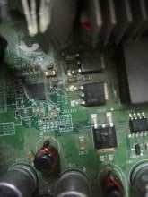
That is impressive.
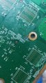
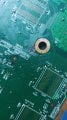
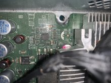
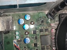
Anyway they don't look like too impedance matched traces* and it does not look like that messed the lower layers up (or at least I can't see anything), so you could probably do jumper wires across them. I would also clean up the trace in the middle one as it looks like it might short something out.
*all those traces around there that do wiggly lines for no particular reason tend to do it either to avoid something noisy on the other side of the board, or to have the same length of trace so all the signals get there at the same time (rather than the minimal resistance you might have encountered in other aspects of board design.
Bonus for you here is the copper being exposed saves you a job of having to scrape off the mask which is usually what troubles the new to it types. If you somehow need more a simple scalpel blade to scrape or fine type stone to abrade tending to be the choices.
Repairing traces has a variety of schools of thought here. If those traces are loose I would glue them down first of all but some will cut back further. You don't have the luxury of pads or vias really for this so it will be in line. Big secret is whatever wire you use (enamelled or kynar being your main two, enamelled you can pull out of an old set of headphones and treat yourself**, kynar you will get to order in at some expense) cut it longer so you can still manipulate it, attach those in the middle and then chop the excess off.
I would probably stagger it a bit more rather than have three in a line potentially shorting each other out or desoldering when you put the next door one on but you should already have that by default.
Practice on something else first as well.
**enamel on the wires (why it often has such bright and shiny colours no normal metal has) needs to be removed. You can burn it off, scrape it off with fine sandpaper or leave it in a molten ball of solder for a while (throw the solder away afterwards) to remove it and get some nice conductive material.

You'll have to scrape a bit of the coating away on the traces you want to connect.
Jump the cut part with a bit of kynar wire, soldering it on both sides of the severed trace.
Jump the cut part with a bit of kynar wire, soldering it on both sides of the severed trace.
I suggest you stop, take it to someone fixing electronics around you and get them to do it. Both Dinoscene and I mentioned multiple methods/things required so if you are not going to read that I doubt you have the patience for electronics fixing.Oky i will try... But use what to make it up???
For reference though you need wire to jump the broken traces (possibly after gluing what remains back down and making sure nothing is shorting another part). They are very fine so your wire needs to be similarly fine, and as you will be soldering close to it without the ability to tape or heatshrink you want wire that won't have its coating melt easily.
There are two main choices
1) Wire called kynar wire. Kynar is a trade name for a certain plastic that does not melt until you get the temperature really high but it is what most electronics vendors and repair places will know it as. Your normal electronics wire is likely not going to be this (kynar is more expensive than basic plastic coatings)
2) Enamel coated wire. They use this in headphones rather than having a massive fat wire. If you have a set of dead headphones then have a look at the wire in these. You will need to get rid of the enamel before soldering.
If you go looking you might see conductive ink and epoxy methods. They are not really suitable here, and rarely that good at the best of times.
Once you have your wire you get to solder it. You will want a reasonable soldering iron for this -- you might have a hard time with an older soldering gun or cheap one you find in a hardware shop. If you can get a wedge tip (rather than a pencil tip) then so much the better. Hot air would be nice but let's not get too silly.
Step 1 is make sure the copper trace is exposed (if the soldermask is still there then you will not have it make contact), but it looks like it is here. If not you would need a scalpel or similar to scrape it off. I would suggest tinning it first too (get some solder on there) as it can make getting a joint far easier.
After this you get to solder it. Personally I like to leave the wire really long so I can control it easily and then chop off the excess when I am done. It is however possible to cut it to the length you need first, expose the ends and then go from there, holding the wire with tweezers.

please someone help me
is this fixable ?
rgh xbox 360
is this fixable ?
rgh xbox 360
Attachments
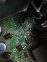
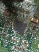
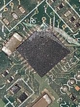
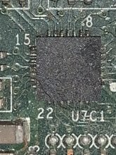
Is that the entire corner of a chip gone? Slip with a screwdriver or something (the bent fins ont the heatsink are also less than ideal)?
Anyway two schools of though here.
1) You replace the whole chip.
2) You find out what the pins now missing did (corners are often simple things like power or earth) and see if you can replicate them.
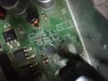
There also looks to be either a ferrite bead or a resistor nearby that is also broken.
Anyway I can't tell from that what type of motherboard it is to know whether the chip in question is paired to that 360 (normally the CPU and the NAND are paired together and need to be swapped out as one).
ON Semiconductor don't do NAND as far as I am aware and won't be doing the CPU so you have that. Whether you can find the chip if you do end up having to replace it on anything other than another 360 board is a different matter.
If doing 2) then you will be in for a tough time -- you either need to find the now broken bond wires and attach to them (does not look like any nice ones here like on older chips -- see some of the cut pin d2b stuff on the wii) or go straight onto the chip itself (ridiculously hard by hand). Hopefully it is a power or ground you can pick up somewhere else (most chips will have a few grounds) and apply with a wire.
Anyway two schools of though here.
1) You replace the whole chip.
2) You find out what the pins now missing did (corners are often simple things like power or earth) and see if you can replicate them.
There also looks to be either a ferrite bead or a resistor nearby that is also broken.
Anyway I can't tell from that what type of motherboard it is to know whether the chip in question is paired to that 360 (normally the CPU and the NAND are paired together and need to be swapped out as one).
ON Semiconductor don't do NAND as far as I am aware and won't be doing the CPU so you have that. Whether you can find the chip if you do end up having to replace it on anything other than another 360 board is a different matter.
If doing 2) then you will be in for a tough time -- you either need to find the now broken bond wires and attach to them (does not look like any nice ones here like on older chips -- see some of the cut pin d2b stuff on the wii) or go straight onto the chip itself (ridiculously hard by hand). Hopefully it is a power or ground you can pick up somewhere else (most chips will have a few grounds) and apply with a wire.
It means that it is impossible to fix it because I have no experience
But I have a RGH that works but it doesn't start up
what can I do ?
And thanks for your quick response
--------------------- MERGED ---------------------------
And yes, I accidentally scratched the board because I was trying to remove the fan
But I have a RGH that works but it doesn't start up
what can I do ?
And thanks for your quick response
--------------------- MERGED ---------------------------
And yes, I accidentally scratched the board because I was trying to remove the fan

That is impressive.
Anyway they don't look like too impedance matched traces* and it does not look like that messed the lower layers up (or at least I can't see anything), so you could probably do jumper wires across them. I would also clean up the trace in the middle one as it looks like it might short something out.
*all those traces around there that do wiggly lines for no particular reason tend to do it either to avoid something noisy on the other side of the board, or to have the same length of trace so all the signals get there at the same time (rather than the minimal resistance you might have encountered in other aspects of board design.
Bonus for you here is the copper being exposed saves you a job of having to scrape off the mask which is usually what troubles the new to it types. If you somehow need more a simple scalpel blade to scrape or fine type stone to abrade tending to be the choices.
Repairing traces has a variety of schools of thought here. If those traces are loose I would glue them down first of all but some will cut back further. You don't have the luxury of pads or vias really for this so it will be in line. Big secret is whatever wire you use (enamelled or kynar being your main two, enamelled you can pull out of an old set of headphones and treat yourself**, kynar you will get to order in at some expense) cut it longer so you can still manipulate it, attach those in the middle and then chop the excess off.
I would probably stagger it a bit more rather than have three in a line potentially shorting each other out or desoldering when you put the next door one on but you should already have that by default.
Practice on something else first as well.
**enamel on the wires (why it often has such bright and shiny colours no normal metal has) needs to be removed. You can burn it off, scrape it off with fine sandpaper or leave it in a molten ball of solder for a while (throw the solder away afterwards) to remove it and get some nice conductive material.
I would simply clean it up, remove any loose traces, jumper the traces using uninsulated strands from a wire, and insulate/fix the jumpers with PCB varnish afterwards. Nail polish will do the trick aswell. If you want to try gluing down the ripped traces, use epoxy, it'll survive the heat when soldering. But as mentioned, there's a variety of schools of thought here, there's no definitive method.
Also don't forget that insulation properties affects the propagation delay aswell, perhaps even more than conductor material/geometry
") If timing in the picosecond range is important, one could try to strip the solder mask from an equal portion of the undamaged traces carrying other parts of the same signal. In practice however, I've never done a repair where I had to take propagation delay into consideration
If timing in the picosecond range is important, one could try to strip the solder mask from an equal portion of the undamaged traces carrying other parts of the same signal. In practice however, I've never done a repair where I had to take propagation delay into consideration A fibre glass brush pen is an indispensable tool for removing solder mask and cleaning up corroded/dirty/burnt traces. A specific model I just love is the Bernstein 2-168
Thank you very much, you saved me, but if there is a video please send the link here
thank you both ❤
I know you didn't mean to me, but you helped me
thank you both ❤
I know you didn't mean to me, but you helped me
Last edited by PLEASE_HELP,
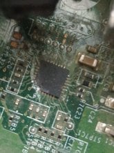
When you say CPU do you actually mean the main processor or just the chip that is broken (possibly plus the resistor/ferrite that might also have been broken in the earlier one)?Can I replace this broken CPU with this one in the picture ?
Replacing the CPU on a 360 can be done but you will also have to replace the NAND (or possibly copy it across, expect to have to do the chip though). It will also involve redoing a BGA which is a nightmare even if you know what you are doing, and will warrant some serious gear (see IR soldering stations and BGA rework devices as you are not going to be able to do that one with a simple hot air station)
To that end if you want to fix the broken chip on the earlier device (I assume it is a nice modded one or something) step one is check the numbers on both the broken one and the replacement one. In this case if they match (just the main chip number -- don't have to be the same batch/datecode/serial) then should be easy enough. If they don't match then you get to look at datasheets for the chip (if you can find them) and figure out if it is a suitable replacement -- sometimes chip makers will make a new version to fix a bug/add some features (higher temperature, better voltage range, higher frequencies supported...) but still be compatible with older stuff.
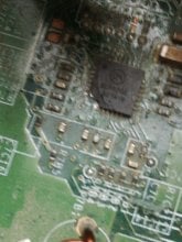
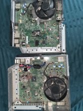
Rotating the picture of the two 360s above around it looks like they are the same motherboard (I don't know them all well enough by sight but most of them change quite a bit between types, the chip down the bottom that is a different size was seemingly made to allow that by having multiple pads) so should be able to cannibalise if you want to roll that way.
Getting the chip off the donor board is a skill, though not a drastic one. I would personally like a hot air station for this sort of thing but you can do it with a soldering iron. Nice bit of flux and some solder wick/braid should get you most places here either way.
While again I would go in for the hot air station approach then soldering it back on should also be doable with a simple soldering iron - see drag soldering.
Practice on something else first (if you are on a thread like this I am assuming you have some dead electronics around somewhere or can find some) or just take it someone that can do this sort of thing (a lot of laptop fixing people will have such abilities these days).
Your RGH machine might also be able to be fixed if it does not start (by which I presume you mean the RGH chip does not work to get you into the hacked dashboard/kernel). Sometimes it can be as simple as redoing a wire or putting a wire in a better location (the noisy thing on the back of the board I mentioned in another reply here -- this RGH lark is one of the better examples we have to point at of such things in general).
When you say CPU do you actually mean the main processor or just the chip that is broken (possibly plus the resistor/ferrite that might also have been broken in the earlier one)?
Replacing the CPU on a 360 can be done but you will also have to replace the NAND (or possibly copy it across, expect to have to do the chip though). It will also involve redoing a BGA which is a nightmare even if you know what you are doing, and will warrant some serious gear (see IR soldering stations and BGA rework devices as you are not going to be able to do that one with a simple hot air station)
To that end if you want to fix the broken chip on the earlier device (I assume it is a nice modded one or something) step one is check the numbers on both the broken one and the replacement one. In this case if they match (just the main chip number -- don't have to be the same batch/datecode/serial) then should be easy enough. If they don't match then you get to look at datasheets for the chip (if you can find them) and figure out if it is a suitable replacement -- sometimes chip makers will make a new version to fix a bug/add some features (higher temperature, better voltage range, higher frequencies supported...) but still be compatible with older stuff.
Rotating the picture of the two 360s above around it looks like they are the same motherboard (I don't know them all well enough by sight but most of them change quite a bit between types, the chip down the bottom that is a different size was seemingly made to allow that by having multiple pads) so should be able to cannibalise if you want to roll that way.
Getting the chip off the donor board is a skill, though not a drastic one. I would personally like a hot air station for this sort of thing but you can do it with a soldering iron. Nice bit of flux and some solder wick/braid should get you most places here either way.
While again I would go in for the hot air station approach then soldering it back on should also be doable with a simple soldering iron - see drag soldering.
Practice on something else first (if you are on a thread like this I am assuming you have some dead electronics around somewhere or can find some) or just take it someone that can do this sort of thing (a lot of laptop fixing people will have such abilities these days).
Your RGH machine might also be able to be fixed if it does not start (by which I presume you mean the RGH chip does not work to get you into the hacked dashboard/kernel). Sometimes it can be as simple as redoing a wire or putting a wire in a better location (the noisy thing on the back of the board I mentioned in another reply here -- this RGH lark is one of the better examples we have to point at of such things in general).
Thank you, you helped me a lot
❤❤
Some solder, plenty of flux, and some 32awg wire
--------------------- MERGED ---------------------------
No, replace that, if not it broke
--------------------- MERGED ---------------------------
Also you'll need a smd/hot air soldering setup to fix this
--------------------- MERGED ---------------------------
After buy it 3 to 5days only
I was try to open that fan holder put this bad happend for motherboard...View attachment 204246 View attachment 204246 View attachment 204246 View attachment 204246
please someone help me
is this fixable ?
rgh xbox 360
No, replace that, if not it broke
--------------------- MERGED ---------------------------
Also you'll need a smd/hot air soldering setup to fix this
New update i soldering the xbox 360 E cut line and finish... It is give read. But the red dot of death still happend.and fan move normal. Is it need reflow. Coz i soldering line after long time.
Never heard of a 360 E benefiting from a reflow (not that reflows are that useful in general) and red ring is just a general failure code (though the specifics can tell you what type). Likely one of the soldering repairs was not successful so go figure out what one that was and redo it.
Similar threads
- Replies
- 14
- Views
- 1K
- Replies
- 7
- Views
- 2K
- Replies
- 1
- Views
- 485
Site & Scene News
New Hot Discussed
-
-
58K views
Nintendo Switch firmware 18.0.0 has been released
It's the first Nintendo Switch firmware update of 2024. Made available as of today is system software version 18.0.0, marking a new milestone. According to the patch... -
28K views
GitLab has taken down the Suyu Nintendo Switch emulator
Emulator takedowns continue. Not long after its first release, Suyu emulator has been removed from GitLab via a DMCA takedown. Suyu was a Nintendo Switch emulator... -
20K views
Atmosphere CFW for Switch updated to pre-release version 1.7.0, adds support for firmware 18.0.0
After a couple days of Nintendo releasing their 18.0.0 firmware update, @SciresM releases a brand new update to his Atmosphere NX custom firmware for the Nintendo...by ShadowOne333 94 -
18K views
Wii U and 3DS online services shutting down today, but Pretendo is here to save the day
Today, April 8th, 2024, at 4PM PT, marks the day in which Nintendo permanently ends support for both the 3DS and the Wii U online services, which include co-op play...by ShadowOne333 176 -
16K views
Denuvo unveils new technology "TraceMark" aimed to watermark and easily trace leaked games
Denuvo by Irdeto has unveiled at GDC (Game Developers Conference) this past March 18th their brand new anti-piracy technology named "TraceMark", specifically tailored...by ShadowOne333 101 -
15K views
GBAtemp Exclusive Introducing tempBOT AI - your new virtual GBAtemp companion and aide (April Fools)
Hello, GBAtemp members! After a prolonged absence, I am delighted to announce my return and upgraded form to you today... Introducing tempBOT AI 🤖 As the embodiment... -
12K views
Pokemon fangame hosting website "Relic Castle" taken down by The Pokemon Company
Yet another casualty goes down in the never-ending battle of copyright enforcement, and this time, it hit a big website which was the host for many fangames based and...by ShadowOne333 65 -
11K views
MisterFPGA has been updated to include an official release for its Nintendo 64 core
The highly popular and accurate FPGA hardware, MisterFGPA, has received today a brand new update with a long-awaited feature, or rather, a new core for hardcore...by ShadowOne333 51 -
11K views
Apple is being sued for antitrust violations by the Department of Justice of the US
The 2nd biggest technology company in the world, Apple, is being sued by none other than the Department of Justice of the United States, filed for antitrust...by ShadowOne333 80 -
10K views
The first retro emulator hits Apple's App Store, but you should probably avoid it
With Apple having recently updated their guidelines for the App Store, iOS users have been left to speculate on specific wording and whether retro emulators as we...
-
-
-
223 replies
Nintendo Switch firmware 18.0.0 has been released
It's the first Nintendo Switch firmware update of 2024. Made available as of today is system software version 18.0.0, marking a new milestone. According to the patch...by Chary -
176 replies
Wii U and 3DS online services shutting down today, but Pretendo is here to save the day
Today, April 8th, 2024, at 4PM PT, marks the day in which Nintendo permanently ends support for both the 3DS and the Wii U online services, which include co-op play...by ShadowOne333 -
169 replies
GBAtemp Exclusive Introducing tempBOT AI - your new virtual GBAtemp companion and aide (April Fools)
Hello, GBAtemp members! After a prolonged absence, I am delighted to announce my return and upgraded form to you today... Introducing tempBOT AI 🤖 As the embodiment...by tempBOT -
146 replies
GitLab has taken down the Suyu Nintendo Switch emulator
Emulator takedowns continue. Not long after its first release, Suyu emulator has been removed from GitLab via a DMCA takedown. Suyu was a Nintendo Switch emulator...by Chary -
101 replies
Denuvo unveils new technology "TraceMark" aimed to watermark and easily trace leaked games
Denuvo by Irdeto has unveiled at GDC (Game Developers Conference) this past March 18th their brand new anti-piracy technology named "TraceMark", specifically tailored...by ShadowOne333 -
96 replies
The first retro emulator hits Apple's App Store, but you should probably avoid it
With Apple having recently updated their guidelines for the App Store, iOS users have been left to speculate on specific wording and whether retro emulators as we...by Scarlet -
94 replies
Atmosphere CFW for Switch updated to pre-release version 1.7.0, adds support for firmware 18.0.0
After a couple days of Nintendo releasing their 18.0.0 firmware update, @SciresM releases a brand new update to his Atmosphere NX custom firmware for the Nintendo...by ShadowOne333 -
80 replies
Apple is being sued for antitrust violations by the Department of Justice of the US
The 2nd biggest technology company in the world, Apple, is being sued by none other than the Department of Justice of the United States, filed for antitrust...by ShadowOne333 -
68 replies
Delta emulator now available on the App Store for iOS
The time has finally come, and after many, many years (if not decades) of Apple users having to side load emulator apps into their iOS devices through unofficial...by ShadowOne333 -
65 replies
Pokemon fangame hosting website "Relic Castle" taken down by The Pokemon Company
Yet another casualty goes down in the never-ending battle of copyright enforcement, and this time, it hit a big website which was the host for many fangames based and...by ShadowOne333
-
Popular threads in this forum
General chit-chat
- No one is chatting at the moment.
-
-
-
-
-
-
-
-
 @
Xdqwerty:
@Purple_Heart, then I will be actually older than him for a bit (ik thats not how ages work btw)
@
Xdqwerty:
@Purple_Heart, then I will be actually older than him for a bit (ik thats not how ages work btw) -
-
-
-
-
-
-
-
-
-
-
-
-
-
-
-
-

