First i apologize for my bad English because it is not my native language.
I decided to open this thread in the idea that it will be useful to the community of this forum.
I am not a great specialist in electronics, but i have some years of experience in microsoldering and especially in reballing. I have seen that there, are enough users who have faced in the process of repairing Switch with pads removed from motherboard in the process of replacement the USB-c port. This happens, when the person performing this operation uses inadequate tools or incorrect settings of the hot air station, namely temperature, the air flow or the flux, etc. I am trying here to present two methods of reconstructing the missing pads from the motherboard to the usb-c port. None of the methods belong to me, i also found them on the internet and i used them successfully in the in the repair process with destroyed usb-c pads.
The first method.
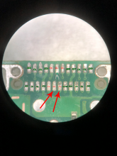
I used a connector ribbon cable and under the microscope i cut the small pieces of copper after i previously peeled them with a surgical knife, about the size of the original pad left on the motherboard. I scraped on the logic board of the switch with a surgical knife in the place where the pad was lifted until i removed the solder mask that covers the circuit and i managed to make the circuit visible. I put a little flux and with the soldering iron i put the tin on the circuit. Then carefully i put a piece of cut copper in the place where the original pad was and carefully fixed it with a little UV solder mask, which i dried quickly with a UV lamp. Then with the soldering iron i made a bridge with tin between the circuit and the new pad implanted on the board. That is how i proceeded to all the lifted pads.
Method two is a bit more complicated.
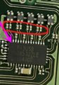
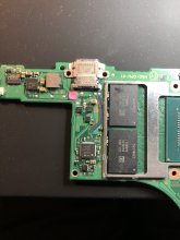
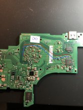
I cut 15mm from the connector ribbon cable and under the microscope, with the soldering iron i solder the circuits directly to the pins on the usb-c port. I mounted the usb-c port on the motherboard and the other end of connector ribbon cable i stuck it on the other side of the usb-c port. I scraped on the ribbon cable and i managed to make the circuit visible. Then i pulled wires from the ribbon contacts to the alternate points on the motherboard as in the diagram below and i isolated with UV solder mask.
Both methods require patience and good microsoldering tools. A microscope or a good magnifying glass will require for a successful operation.


 ]
]


UPDATE ! : REFOX Soldering Lug For Pads Repair !
https://shop.rewa.tech/detail/refox...KupSHYOTN04Zi2htRHS2aNjfjG8Dd0SboalP_pAGBjzKY
I decided to open this thread in the idea that it will be useful to the community of this forum.
I am not a great specialist in electronics, but i have some years of experience in microsoldering and especially in reballing. I have seen that there, are enough users who have faced in the process of repairing Switch with pads removed from motherboard in the process of replacement the USB-c port. This happens, when the person performing this operation uses inadequate tools or incorrect settings of the hot air station, namely temperature, the air flow or the flux, etc. I am trying here to present two methods of reconstructing the missing pads from the motherboard to the usb-c port. None of the methods belong to me, i also found them on the internet and i used them successfully in the in the repair process with destroyed usb-c pads.
The first method.
I used a connector ribbon cable and under the microscope i cut the small pieces of copper after i previously peeled them with a surgical knife, about the size of the original pad left on the motherboard. I scraped on the logic board of the switch with a surgical knife in the place where the pad was lifted until i removed the solder mask that covers the circuit and i managed to make the circuit visible. I put a little flux and with the soldering iron i put the tin on the circuit. Then carefully i put a piece of cut copper in the place where the original pad was and carefully fixed it with a little UV solder mask, which i dried quickly with a UV lamp. Then with the soldering iron i made a bridge with tin between the circuit and the new pad implanted on the board. That is how i proceeded to all the lifted pads.
Method two is a bit more complicated.
I cut 15mm from the connector ribbon cable and under the microscope, with the soldering iron i solder the circuits directly to the pins on the usb-c port. I mounted the usb-c port on the motherboard and the other end of connector ribbon cable i stuck it on the other side of the usb-c port. I scraped on the ribbon cable and i managed to make the circuit visible. Then i pulled wires from the ribbon contacts to the alternate points on the motherboard as in the diagram below and i isolated with UV solder mask.
Both methods require patience and good microsoldering tools. A microscope or a good magnifying glass will require for a successful operation.
] UPDATE ! : REFOX Soldering Lug For Pads Repair !
https://shop.rewa.tech/detail/refox...KupSHYOTN04Zi2htRHS2aNjfjG8Dd0SboalP_pAGBjzKY
Last edited by FXDX,


 this really helps a lot