


Ah okay thanks! Well than it's not really useful in my case. I don't use the switch as a portable console, it's always in dock mode.Correct")
You are using an out of date browser. It may not display this or other websites correctly.
You should upgrade or use an alternative browser.
You should upgrade or use an alternative browser.
- Thread starter MatinatorX
- Start date
- Views 344,772
- Replies 1,396
- Likes 177
- Status
- Not open for further replies.

Ah okay thanks! Well than it's not really useful in my case. I don't use the switch as a portable console, it's always in dock mode.
that's fine, It's still a cool project though, and as I said, maybe possible in future
It would be really nice if it were possible to inject the payload from the game card slot. I will follow this projectthat's fine, It's still a cool project though, and as I said, maybe possible in future
Yeah it comes down to if the gamecard reader is cracked from everything I knowIt would be really nice if it were possible to inject the payload from the game card slot. I will follow this project
- Joined
- May 29, 2016
- Messages
- 1,511
- Trophies
- 0
- Age
- 29
- Location
- Madrid
- Website
- manuelrodriguezmatesanz.com
- XP
- 2,790
- Country

In the card slot you have the jig and the dongle. You use the jig in the joycon rail and the dongle in usb-c slotSo the jig is in the game card and I would need to remove the card from the slot and attach it under the switch at the usb-c port?


Quick update: battery test stream went well - we saw way over the previous injection count, with about 1350 injections on a single Energizer CR1216 battery! This should last most people well over a year, and with the auto-power off now working great and button cell batteries having incredible shelf life, battery drain when not in use should be almost nonexistent.
So, what's next?
The sticker design is done, but I still have to finish the case art. I want to have that done by the end of this week, with stickers, art, and cases themselves being ordered on Friday. This weekend will be spend building the tester units.
I wanted to send the tester units out this week, but it wouldn't really be fair to send them out without the stickers, case and art insert. I will be waiting until those arrive so I can send the testers a complete package. Also, this means I can still get a solid 6 hours of sleep this week.
I've decided to forgo having a separate case design for the buttonless version, and instead just provide two stickers with each DragonInjector - one with and one without holes and labels for the buttons. This simplifies assembly and the user can then decide which sticker they want to apply. The buttons will just be hidden behind the sticker, but it will end up looking the same as if I omitted them completely. It also means I don't have to have two different products to keep track of. As the buttons will likely be a feature used by those a little deeper into the Switch scene, the DragonInjector will ship with ArgonNX preloaded, with instructions on how to swap to @mattytrog 's firmware written inside the art insert.
The firmware for the "buttonless" version is done except for the low battery check. I'd like to have both firmwares tested and working by early next week, with a video of each posted to the YouTube channel I created because Discord has a 40mb upload limit in 2019 for some reason. You can find it here: https://www.youtube.com/channel/UCbq2Mc-UeaTiMOJ--NiQ_-Q
Thanks again everyone for the kind words and support!

Well done sir!Quick update: battery test stream went well - we saw way over the previous injection count, with about 1350 injections on a single Energizer CR1216 battery! This should last most people well over a year, and with the auto-power off now working great and button cell batteries having incredible shelf life, battery drain when not in use should be almost nonexistent.
So, what's next?
The sticker design is done, but I still have to finish the case art. I want to have that done by the end of this week, with stickers, art, and cases themselves being ordered on Friday. This weekend will be spend building the tester units.
I wanted to send the tester units out this week, but it wouldn't really be fair to send them out without the stickers, case and art insert. I will be waiting until those arrive so I can send the testers a complete package. Also, this means I can still get a solid 6 hours of sleep this week.
I've decided to forgo having a separate case design for the buttonless version, and instead just provide two stickers with each DragonInjector - one with and one without holes and labels for the buttons. This simplifies assembly and the user can then decide which sticker they want to apply. The buttons will just be hidden behind the sticker, but it will end up looking the same as if I omitted them completely. It also means I don't have to have two different products to keep track of. As the buttons will likely be a feature used by those a little deeper into the Switch scene, the DragonInjector will ship with ArgonNX preloaded, with instructions on how to swap to @mattytrog 's firmware written inside the art insert.
The firmware for the "buttonless" version is done except for the low battery check. I'd like to have both firmwares tested and working by early next week, with a video of each posted to the YouTube channel I created because Discord has a 40mb upload limit in 2019 for some reason. You can find it here: https://www.youtube.com/channel/UCbq2Mc-UeaTiMOJ--NiQ_-Q
Thanks again everyone for the kind words and support!
View attachment 155912
What pin are you using for LED?
Time to add support for it in Simple-UF2 unless Trinket is correct already
Well done sir!
What pin are you using for LED?
Time to add support for it in Simple-UF2 unless Trinket is correct already
Praise from the master themself, thanks buddy!
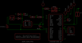
Pinout is as follows, but I had planned to modify your code instead of asking you to do the work so don't feel obligated in any way.
LED is a 1mm x 1mm RGB LED (bugger to hand solder) and is common anode, so lines must be pulled low to turn on and high to turn off.
D7 = Red
D8 = Green
D2 = Blue
I have D0 (the + button) accepting 3.3v through S1 whenever pressed which also turns on LDO to wake up the MCU. The idea is whenever the MCU starts, it checks to see if D0 is HIGH, and if so it increments the payload number, writes it to eeprom, skips injection, blinks blue to indicate the number of the payload selected then goes to sleep. The idea is to hold the button until the LED stops flashing.
Also have A0 reading battery voltage through a voltage divider. R1 is 2.5MΩ and R2 is 1MΩ, which converts 0-3.85v from battery to 0-1.1v at A0 to match the internal 1.1v reference of the ATSAMD21. The plan is to have a low battery LED indication of 0.5 seconds on boot. I have yet to map out the voltages I want to use for battery status, but colors would be green for healthy, yellow for warning and red for critical battery level. On red I would skip injection and just flash red a few times before putting MCU to sleep. Reason being, injection can fail if voltage is too low, which causes the Switch to freeze, requiring a 20sec power button shutdown. Advanced users who want to risk it for a few more injections can modify the firmware.
Schemmy attached. I've been told my schematics look awful, so sorry about that.
Attachments
Last edited by MatinatorX,
Praise from the master themself, thanks buddy!
Pinout is as follows, but I had planned to modify your code instead of asking you to do the work so don't feel obligated in any way.
LED is a 1mm x 1mm RGB LED (bugger to hand solder) and is common anode, so lines must be pulled low to turn on and high to turn off.
D7 = Red
D8 = Green
D2 = Blue
I have D0 (the + button) accepting 3.3v through S1 whenever pressed which also turns on LDO to wake up the MCU. The idea is whenever the MCU starts, it checks to see if D0 is HIGH, and if so it increments the payload number, writes it to eeprom, skips injection, blinks blue to indicate the number of the payload selected then goes to sleep. The idea is to hold the button until the LED stops flashing.
Also have A0 reading battery voltage through a voltage divider. R1 is 2.5MΩ and R2 is1MΩ, which converts 0-3.85v from battery to 0-1.1v at A0 to match the internal 1.1v reference of the ATSAMD21. The plan is to have a low battery LED indication of 0.5 seconds on boot. I have yet to map out the voltages I want to use for battery status, but colors would be green for healthy, yellow for warning and red for critical battery level. On red I would skip injection and just flash red a few times before putting MCU to sleep. Reason being, injection can fail if voltage is too low, which causes the Switch to freeze, requiring a 20sec power button shutdown. Advanced users who want to risk it for a few more injections can modify the firmware.
Schemmy attached. I've been told my schematics look awful, so sorry about that.
Thank-you sir!
I go off the Atmel pin numbers but I`ll sort that!
Will work on it when I got my lad in bed. I love your device!
Thank-you sir!
I go off the Atmel pin numbers but I`ll sort that!
Will work on it when I got my lad in bed. I love your device!
Well aren't you fancy then.
D7 = PA00
D8 = PA01
D2 = PA09
D0 = PA08
A0 = PA02
Thanks for the kind words! I love your firmware.
Fancy? Nah...Well aren't you fancy then.
D7 = PA00
D8 = PA01
D2 = PA09
D0 = PA08
A0 = PA02
Thanks for the kind words! I love your firmware.
Just making a JSON and variant files for armoured-dildo (arduino)
What PID / VID are you using sir? Your own or trinket / gemma / sparkfun whatever?
EDIT: Don`t matter. Solved
Last edited by mattytrog,
Fancy? Nah...
Just making a JSON and variant files for armoured-dildo (arduino)
What PID / VID are you using sir? Your own or trinket / gemma / sparkfun whatever?
EDIT: Don`t matter. Solved
I'm still flashing the stock Trinket M0 Arduino bootloader with OpenOCD, haven't had time to mess with it yet, so VID and PID will be the Trinket M0 one still. Eventually I want to rename the flash drive to DRAGONBOOT and put the code for the battery indicator light in there too, but I haven't had the chance to mess with it yet. Do you know if it's possible to update the bootloader through Arduino or the UF2 files?
Last edited by MatinatorX,
@Pixel
I'm still flashing the stock Trinket M0 Arduino bootloader with OpenOCD, haven't had time to mess with it yet, so VID and PID will be the Trinket M0 one still. Eventually I want to rename the flash drive to DRAGONBOOT and put the code for the battery indicator light in there too, but I haven't had the chance to mess with it yet. Do you know if it's possible to update the bootloader through Arduino or the UF2 files?
Use UF2 files
So... Going to work on battery voltage routines tonight.
The SAMD21 tends to drop out at about 2.2v (I think if I remember correctly)
So, looking at the 1216 discharge curve here, I`d initially go for 2600mV amber, 2400mV red >>> shutdown
Will have a play throughout the evening
So, if we say (through the divider), 3000mV (1216 nominal v) / 1100mV (going to analogue pin) gives 2.72 as a ratio
If we apply that to the values above...
2600 / 2.72 = 955mV amber
2400 / 2.72 = 882mV red
Just to get us going... Right... Need to go digging for a rheostat in my box of shit now
Not taking current into account yet with above figures.
Going to enjoy this.
Last edited by mattytrog,
So... Going to work on battery voltage routines tonight.
The SAMD21 tends to drop out at about 2.2v (I think if I remember correctly)
So, looking at the 1216 discharge curve here, I`d initially go for 2600mV amber, 2400mV red >>> shutdown
Will have a play throughout the evening
So, if we say (through the divider), 3000mV (1216 nominal v) / 1100mV (going to analogue pin) gives 2.72 as a ratio
If we apply that to the values above...
2600 / 2.72 = 955mV amber
2400 / 2.72 = 882mV red
Just to get us going... Right... Need to go digging for a rheostat in my box of shit now
Not taking current into account yet with above figures.
Going to enjoy this.
I just want to note that my intention was to make less work for you, not more. But I am sincerely glad you're enjoying it.
I really do appreciate the help. My plan was going to be to stick my multimeter on GND and V and leave my Switch injecting payloads all night on video, then look at the video to see what the voltage was at 1000 injections and set that as amber, then again at 1200 injections and set that as red. (From testing I know that we average 1300-1350 injections on a single CR1216.)
I'm not sure that the 2.2V brownout threshold will be an accurate representation of "0 percent" battery life though, since the ATSAMD21 is only capable of Full Speed USB and not High Speed USB, which (as I understand it, I could be very wrong) uses different rules for a logical 1 or 0. While High Speed USB only cares about a 200mV differential to indicate a logical 1 and 0, Full Speed USB has set values of 0.3v and 2.8v, above and below which act as a logical 0 or 1. While I think these values can probably be fudged a bit, in my tests, even when the ATSAMD21 itself is still operating just fine, once voltage drops below 2.7V injections start to fail.
I had also planned to read voltage before starting USB on the MCU, as there's a massive spike in current with USB on and it could easily fudge the readings. While injecting I observe 11-13mA of current but it's under 1mA when running with USB off.
Anyways, if I haven't said it enough, I really do appreciate the help as my free time is severely limited and everyone has been way too p[atient waiting for me to deliver. Cheers!

Last edited by MatinatorX,
Fair enough mate. You know your device.I just want to note that my intention was to make less work for you, not more. But I am sincerely glad you're enjoying it.
I really do appreciate the help. My plan was going to be to stick my multimeter on GND and V and leave my Switch injecting payloads all night on video, then look at the video to see what the voltage was at 1000 injections and set that as amber, then again at 1200 injections and set that as red. (From testing I know that we average 1300-1350 injections on a single CR1216.)
I'm not sure that the 2.2V brownout threshold will be an accurate representation of "0 percent" battery life though, since the ATSAMD21 is only capable of Full Speed USB and not High Speed USB, which (as I understand it, I could be very wrong) uses different rules for a logical 1 or 0. While High Speed USB only cares about a 200mV differential to indicate a logical 1 and 0, Full Speed USB has set values of 0.3v and 2.8v, above and below which act as a logical 0 or 1. While I think these values can probably be fudged a bit, in my tests, even when the ATSAMD21 itself is still operating just fine, once voltage drops below 2.7V injections start to fail.
I had also planned to read voltage before starting USB on the MCU, as there's a massive spike in current with USB on and it could easily fudge the readings. While injecting I observe 11-13mA of current but it's under 1mA when running with USB off.
Anyways, if I haven't said it enough, I really do appreciate the help as my free time is severely limited and everyone has been way too p[atient waiting for me to deliver. Cheers!
Written battery code... Thought I had a 10k rheostat in my boxes of crap but nope. Time to strip an old radio tomorrow.
I like your potential divider idea
No the 2.2v isn`t accurate at all. That was the voltage the thing actually started locking up in deep sleep.
Was just a figure I had in my very-bad-sectored brain. I think that was actually the brownout for the LDO on the trinket thinking about it some more.
My notes are in the workshop / shed / secret whiskey drinking hole and I`m bloody frozen. Can`t get warm. So I`ll go over them tomorrow.
So, in the meantime, just put another feature into my Franken-Hekate. Backup prodinfo only. If people are too impatient for a full dump.
Will be in 0.9.7 of Simple-UF2.
It`s nice having something to do!

Thickness, sir.Lithum Battery will not be better ?
Regards Wolf
A 2032 is too thick.
- Status
- Not open for further replies.
Similar threads
- Replies
- 15
- Views
- 8K
- Replies
- 10
- Views
- 6K
- Replies
- 1
- Views
- 706
- Replies
- 11
- Views
- 8K
- Replies
- 18
- Views
- 6K
Site & Scene News
New Hot Discussed
-
-
58K views
Nintendo Switch firmware 18.0.0 has been released
It's the first Nintendo Switch firmware update of 2024. Made available as of today is system software version 18.0.0, marking a new milestone. According to the patch... -
29K views
GitLab has taken down the Suyu Nintendo Switch emulator
Emulator takedowns continue. Not long after its first release, Suyu emulator has been removed from GitLab via a DMCA takedown. Suyu was a Nintendo Switch emulator... -
21K views
Atmosphere CFW for Switch updated to pre-release version 1.7.0, adds support for firmware 18.0.0
After a couple days of Nintendo releasing their 18.0.0 firmware update, @SciresM releases a brand new update to his Atmosphere NX custom firmware for the Nintendo...by ShadowOne333 94 -
18K views
Wii U and 3DS online services shutting down today, but Pretendo is here to save the day
Today, April 8th, 2024, at 4PM PT, marks the day in which Nintendo permanently ends support for both the 3DS and the Wii U online services, which include co-op play...by ShadowOne333 176 -
15K views
GBAtemp Exclusive Introducing tempBOT AI - your new virtual GBAtemp companion and aide (April Fools)
Hello, GBAtemp members! After a prolonged absence, I am delighted to announce my return and upgraded form to you today... Introducing tempBOT AI 🤖 As the embodiment... -
12K views
Pokemon fangame hosting website "Relic Castle" taken down by The Pokemon Company
Yet another casualty goes down in the never-ending battle of copyright enforcement, and this time, it hit a big website which was the host for many fangames based and...by ShadowOne333 65 -
11K views
MisterFPGA has been updated to include an official release for its Nintendo 64 core
The highly popular and accurate FPGA hardware, MisterFGPA, has received today a brand new update with a long-awaited feature, or rather, a new core for hardcore...by ShadowOne333 51 -
11K views
Apple is being sued for antitrust violations by the Department of Justice of the US
The 2nd biggest technology company in the world, Apple, is being sued by none other than the Department of Justice of the United States, filed for antitrust...by ShadowOne333 80 -
10K views
The first retro emulator hits Apple's App Store, but you should probably avoid it
With Apple having recently updated their guidelines for the App Store, iOS users have been left to speculate on specific wording and whether retro emulators as we... -
9K views
"TMNT: The Hyperstone Heist" for the SEGA Genesis / Mega Drive gets a brand new DX romhack with new features
The romhacking community is always a source for new ways to play retro games, from completely new levels or stages, characters, quality of life improvements, to flat...by ShadowOne333 36
-
-
-
223 replies
Nintendo Switch firmware 18.0.0 has been released
It's the first Nintendo Switch firmware update of 2024. Made available as of today is system software version 18.0.0, marking a new milestone. According to the patch...by Chary -
176 replies
Wii U and 3DS online services shutting down today, but Pretendo is here to save the day
Today, April 8th, 2024, at 4PM PT, marks the day in which Nintendo permanently ends support for both the 3DS and the Wii U online services, which include co-op play...by ShadowOne333 -
169 replies
GBAtemp Exclusive Introducing tempBOT AI - your new virtual GBAtemp companion and aide (April Fools)
Hello, GBAtemp members! After a prolonged absence, I am delighted to announce my return and upgraded form to you today... Introducing tempBOT AI 🤖 As the embodiment...by tempBOT -
146 replies
GitLab has taken down the Suyu Nintendo Switch emulator
Emulator takedowns continue. Not long after its first release, Suyu emulator has been removed from GitLab via a DMCA takedown. Suyu was a Nintendo Switch emulator...by Chary -
96 replies
The first retro emulator hits Apple's App Store, but you should probably avoid it
With Apple having recently updated their guidelines for the App Store, iOS users have been left to speculate on specific wording and whether retro emulators as we...by Scarlet -
94 replies
Atmosphere CFW for Switch updated to pre-release version 1.7.0, adds support for firmware 18.0.0
After a couple days of Nintendo releasing their 18.0.0 firmware update, @SciresM releases a brand new update to his Atmosphere NX custom firmware for the Nintendo...by ShadowOne333 -
80 replies
Apple is being sued for antitrust violations by the Department of Justice of the US
The 2nd biggest technology company in the world, Apple, is being sued by none other than the Department of Justice of the United States, filed for antitrust...by ShadowOne333 -
74 replies
Delta emulator now available on the App Store for iOS
The time has finally come, and after many, many years (if not decades) of Apple users having to side load emulator apps into their iOS devices through unofficial...by ShadowOne333 -
65 replies
Pokemon fangame hosting website "Relic Castle" taken down by The Pokemon Company
Yet another casualty goes down in the never-ending battle of copyright enforcement, and this time, it hit a big website which was the host for many fangames based and...by ShadowOne333 -
53 replies
Nintendo "Indie World" stream announced for April 17th, 2024
Nintendo has recently announced through their social media accounts that a new Indie World stream will be airing tomorrow, scheduled for April 17th, 2024 at 7 a.m. PT...by ShadowOne333
-
Popular threads in this forum
General chit-chat
- No one is chatting at the moment.
-
-
-
-
-
-
-
-
-
-
-
-
-
-
-
-
-
-
-
-
 @
RedColoredStars:
There is an actual trailer with footage too. lol. Going to watch it tonight. Grabbed it from... a place.
@
RedColoredStars:
There is an actual trailer with footage too. lol. Going to watch it tonight. Grabbed it from... a place. -
-
 @
SylverReZ:
@Psionic Roshambo, JonTron's back yet again until he disappears into the void for another 6 or so months.+1
@
SylverReZ:
@Psionic Roshambo, JonTron's back yet again until he disappears into the void for another 6 or so months.+1 -
-
-