Hardware Removed top screen of 3DS XL, here's what I know so far

zeello

The reason we can't have nice things.
OP
Member
Joined
Apr 15, 2013
Messages
774
Trophies
1
XP
1,223
Country
United States
I finally dismantled my 3DS XL. What I did next was reassemble it "disembodied" - make the system run with both halves disconnected. (exposed ribbon cables running from one to the other) The system functioned as normal. So then I proceeded to disconnect things one by one to see to see when the system no longer powers on.

Exactly 4 things run from the bottom screen to the top:
- wifi cable
- camera ribbon cable
- the screen
- speaker ribbon cable

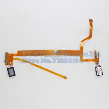
Unlike the DSi however, the top screen essentially has 2 ribbon cables, since the speaker ribbon cable is connected to the motherboard AND the top screen. Bad news, right? Well here's the thing... I found that the system powers on with only the speaker ribbon cable attached, provided the speaker ribbon is attached to the top screen. (the top screen doesn't display anything while in this state, but the system runs as normal and even the speakers work!) Here's a diagram:

7jx9.jpg

The top screen connects to the speaker ribbon cable on two points (white ribbon cable connectors):
- connecting to the top one does nothing (system does not power on)
- connecting to the bottom one makes the system power on (bottom screen works, speakers work, top screen does not work)
[edit: yea, I might've messed up the orientation of some objects in the image.. obv the right speaker is on top, for instance. Rest assured though there are 2 ribbon cable connectors on the right speaker board, and of those 2, the one closer to the bottom screen makes the system power on.]

It is a funny thing, while working on this, I had an idea for some Troll Science.
Seeing as someone made their DS Lite run without top screen by putting a resistor on the top screen ribbon cable...... can't I just pour solder (or resistive glue) over the entire ribbon cable connector, and just poke a resistor into the whole glob? :rofl:

Well, obviously I wouldn't do that, without first seeking guidance from the forum. Because if I do that, there's no taksies backsies... if it doesn't work, I've ruined the system. (and thus far, I had not broken any part of my 3DS XL... I was still at a point where I can choose to reassemble the entire system like nothing ever happened)

But as long as I wasn't using solder, I thought it wouldn't hurt to test it. I jammed a resistor into that ribbon cable connection with my fingers... didn't work.... tried again... and I found that the resistor was kinda jammed in. (I no longer needed to hold it) I push the power button... and lo and behold it worked!!

Anyway... dunno how to close this post. I'm still not finished, and I'm considering putting the resistor someplace else. And another issue is fitting everything inside the bottom half. I noticed something about DSi and 3DS XL... wherever there could have been room to put stuff inside, Nintendo fills that part with casing... Look at the inside of the case, there is tons of plastic protrusions that serve no purpose. If only there was a way to shave those off...
 
  • Like
Reactions: user64

Cartmanuk

Well-Known Member
Member
Joined
Nov 20, 2010
Messages
720
Trophies
1
XP
409
Country
Lol handy to know maybe this can help people fault find maybe.
Good luck with your experimenting.
Try not to break your 3DS.
 
  • Like
Reactions: zeello

Shinitai

Well-Known Member
Newcomer
Joined
Dec 17, 2013
Messages
86
Trophies
0
XP
180
Country
Uruguay
It is a funny thing, while working on this, I had an idea for some Troll Science.
Seeing as someone made their DS Lite run without top screen by putting a resistor on the top screen ribbon cable...... can't I just pour solder (or resistive glue) over the entire ribbon cable connector, and just poke a resistor into the whole glob?
Why would you want to do that though?
 

zeello

The reason we can't have nice things.
OP
Member
Joined
Apr 15, 2013
Messages
774
Trophies
1
XP
1,223
Country
United States
here's a proper photo of that ribbon cable: (not mine, found on google)
Control-LCD-Speaker-Flex-Ribbon-Cable-for-3DS-LL-3DS-XL.jpg_350x350.jpg


People seem to be selling them on ebay... Maybe I will buy one. By using a spare, I can do as much damage as I want.
 

Foxi4

Endless Trash
Global Moderator
Joined
Sep 13, 2009
Messages
30,825
Trophies
3
Location
Gaming Grotto
XP
29,840
Country
Poland
Of course the system won't power on - the circuit is incomplete. You have to match the resistance of the top half on all of the points that used to be connected together and close the circuit. You'll need a miltimeter and quite a bit of spare time, perhaps some breadboards as well until you nail it.
It is a funny thing, while working on this, I had an idea for some Troll Science.
Seeing as someone made their DS Lite run without top screen by putting a resistor on the top screen ribbon cable...... can't I just pour solder (or resistive glue) over the entire ribbon cable connector, and just poke a resistor into the whole glob? :rofl:
If you want to short the system and possibly blow a couple fuses/other components, sure - dab it in as much solder as you want. In all other cases, check the pin-outs to know what exactly you're supposed to connect and with what resistence. :rofl2:
 

zeello

The reason we can't have nice things.
OP
Member
Joined
Apr 15, 2013
Messages
774
Trophies
1
XP
1,223
Country
United States
Of course the system won't power on - the circuit is incomplete. You have to match the resistance of the top half on all of the points that used to be connected together and close the circuit. You'll need a miltimeter and quite a bit of spare time, perhaps some breadboards as well until you nail it.
Yes but, as I have said, I found a place to stick the resistor to make the system work.
Here's one option I have:
- remove speakers, and cut the ribbon cable parts which I don't need.
In other words here is what the ribbon cable will look like:
67t4.jpg

Then I put conductive glue in one of the white boxes (ribbon cable connectors) and just stick a resistor in it.

Then it's simply a matter of fitting it in the bottom half.
That should work, right?

If you want to short the system and possibly blow a couple fuses/other components, sure - dab it in as much solder as you want. In all other cases, check the pin-outs to know what exactly you're supposed to connect and with what resistence. :rofl2:
But let's say the glue is not touching any other part of the motherboard.. just the ribbon cable connector pins.. And then I stick a resistor in it... You're saying it won't work?

Blowing a fuse sounds scary... I don't want to damage my system in a way where I can't easily replace a part.
 

Foxi4

Endless Trash
Global Moderator
Joined
Sep 13, 2009
Messages
30,825
Trophies
3
Location
Gaming Grotto
XP
29,840
Country
Poland
I'm saying that you are running into the risk of connecting the positive and negative terminals on the ribbon which are undoubtedly there - ribbons are tiny, y'see. :P You're probably better off skipping the ribbon completely and working on the PCB terminals.

Moreover, connecting just about any resistor will work only temporarily if at all - you need to calculate how much actual resistance you need.

I would definitely investigate into the possibility of keeping the speakers and fitting them on the bottom half, perhaps by increasing its thickness, and completing the screen circuit with an appropriate resistor. :)
 

zeello

The reason we can't have nice things.
OP
Member
Joined
Apr 15, 2013
Messages
774
Trophies
1
XP
1,223
Country
United States
I'm saying that you are running into the risk of connecting the positive and negative terminals on the ribbon which are undoubtedly there - ribbons are tiny, y'see. :P You're probably better off skipping the ribbon completely and working on the PCB terminals.
On DSi I know which 2 points to use... When applying a resistor to it, I made 2 globs of glue and tried to keep them from touching each other.

On 3DS XL, all I know is, I jammed a resistor in one of the tiny white flex cable connectors on the speaker flex cable, and it worked... I even played a little while in this state, and nothing gave way.
Admittedly, I did not use glue yet... and the resistor was probably not in contact with itself.... but I want to believe that it will work.

What does it matter if I mix positive and negative?
And what is a "short"? I just hope I haven't shorted anything already.
 

Foxi4

Endless Trash
Global Moderator
Joined
Sep 13, 2009
Messages
30,825
Trophies
3
Location
Gaming Grotto
XP
29,840
Country
Poland
...if you connect the positive and negative terminals together without anything in-between, you'll short the circuit. By "shorted circuit" I mean connecting two leads of the circuit which are not meant to be connected together and may cause damage to the system.

I know you "want to believe" but before you start projects like this, you need to have some basic knowlege behind you. Right now it really sounds like you're going to break the system.

EDIT: Long story short not to waste anyone's time - you need to know the pin-out of the ribbon in question, then you need to know the resistance of the top screen and get a matching resistor to complete that circuit. Repeat the process with the speakers and other components unless you want to use them, in which case you will have to tinker out a way to complete those circuits as well without replacing the components with resistors.

If you use an incorrect resistor, you will either have too little or too much resistance on the circuit and you will inevitably damage some components - here's for hoping that it'd be the resistor you added.

For these kinds of fun you need precision, a good soldering iron and a multimeter at the very least. It's infinitely better to solder on the terminals themselves rather than use glue on the ribbon.

With your current tools and know-how, I strongly discourage you from proceeding. Read up on the matter first, consult the pro's and then work on this. ;)
 

zeello

The reason we can't have nice things.
OP
Member
Joined
Apr 15, 2013
Messages
774
Trophies
1
XP
1,223
Country
United States
EDIT: Long story short not to waste anyone's time - you need to know the pin-out of the ribbon in question, then you need to know the resistance of the top screen and get a matching resistor to complete that circuit. Repeat the process with the speakers and other components unless you want to use them, in which case you will have to tinker out a way to complete those circuits as well without replacing the components with resistors.
Everyone else doing the mod with a DS Lite doesn't do anything you are recommending. For instance, most modders remove the speakers and simply leave it at that. They use only one resistor (or only one LED) and its sole purpose is to make the system think a top screen is attached. They don't close the connection for other things like speakers because it isn't needed to get the system working.

Personally the modders don't seem to treat the resistor wattage as rocket science either, they seem to act like it is more a matter of trial and error.
http://www.acidmods.com/forum/index.php/topic,21816.0.html

The modders on youtube seem to never specify the wattage of the resistor. They might say it is a 1k resistor but never mention its wattage. (dunno why)
Also, one modder says the DS Lite screen is 22k. So he uses a 1k resistor, which he says should be good enough!

13:00 "I soldered a 1k ohm resistor to here"
13:10 "I actually measured the voltage of the screen, and I think the screen was maybe 22k"

1k resistor for a 22k screen!!
I guess when you say I need to match the two, that means to divide by 22!

That said, all modders seem to attach a resistor/LED to the motherboard, not the ribbon cable. Rs1n being the only exception.
Admittedly, none of them seem to mix positive and negative currents, meaning if I do that, I would be the only one.

It's infinitely better to solder on the terminals themselves rather than use glue on the ribbon.
What about using glue on the terminals themselves?
Glue is way better than solder.
Personally I like the idea of using ribbon cables since those are cheaper to replace. If I work on the motherboard I might muck something up.
But I just thought of something... if I used a continuity tester to find a current... how will I know it's the top screen current? All I would know is that it's a current, but not the one needed to get the system to power on.
 

Foxi4

Endless Trash
Global Moderator
Joined
Sep 13, 2009
Messages
30,825
Trophies
3
Location
Gaming Grotto
XP
29,840
Country
Poland
Fair enough, use a small resistor to complete the circuit, perhaps it'll actually lead to extending battery life - I would definitely try to match the resistance of the missing component so that the system operates at what's called "nominal values", but this might work fine since it does close the circuit, just not in a way that was expected by the designers.

The reason why you use resistors in the first place is to lower the so-called current density in order not to allow too many Ampers to go through a following component - more on Ohm's law here. By using an inappropriate resistor, you can push through too many or too little Ampers which may have an adverse effect on the rest of the circuit - this is why we measure this stuff. 1k seems like plenty and if the screen was the only component in that circuit, you should be in the clear, but alas, I would measure the screen.

As for using glue, if you like ribbon cables hanging out, sure - do that as long as you don't care how the monstrosity looks like visually - I assumed you would.

"Other modders" are not closing other circuits because they don't care about other peripherals. You only need to close the screen one to enable the system, sure enough, that's what the LCD driver requires to start up, but not closing other circuits means that the speakers, the WiFi module and the cameras will not work, meaning you're stripping the system off its functionality, which is why I recommended completing those circuits.

Also, not "wattage" of resistors. Resistance is measured in Ohms.

Just out of plain curiousity though, what do you plan to do with that 3DS XL? It won't play GBA games like the modded DS Lite - it doesn't have a GBA slot... I fail to see purpose beyond the level of an experiment. :unsure:
 

zeello

The reason we can't have nice things.
OP
Member
Joined
Apr 15, 2013
Messages
774
Trophies
1
XP
1,223
Country
United States
I just thought of something... as I've said, I already got the 3DS XL to work by jamming the resistor in the white flex-cable connector on the speaker flex cable. I believe this works. You are scaring me by saying I will mix positive and negative, but I believe my method was legit. Therefore what I will do is use that same method that worked, but either apply very little glue (two separate spots, with the glue not touching each other) or simply tape the resistor in place. (or better yet I'd do both) Maybe I'd use glue on one point instead of two, this way it would be impossible to have 2 points of glue touching each other.

I just hope I didn't short my system already without realizing it.
But part of me wishes not to believe the system could be so fragile!
None of the other modders say their system was shorted, and they aren't afraid to keep poking around until it works.

As for using glue, if you like ribbon cables hanging out, sure - do that as long as you don't care how the monstrosity looks like visually - I assumed you would.
oh but I do care!
I will stuff the ribbon cable in the bottom half.
And the wifi cable. (maybe I could find a way to shorten this somehow)
Nothing would be sticking out.

Also, not "wattage" of resistors. Resistance is measured in Ohms.
Ok, but my resistors are
1k half watt
1.5k half watt
1.3k quarter watt
What's with the half/quarter watt? And when I go to buy them, why does the guy ask me what kind of wattage I need? o.O

Just out of plain curiousity though, what do you plan to do with that 3DS XL?
If I start answering this, the thread will degenerate into an argument over whether the mod is stupid, and then the thread will get locked. (because that is what happened last time)
So instead I'll just say that I very much appreciate your advice.
 

Foxi4

Endless Trash
Global Moderator
Joined
Sep 13, 2009
Messages
30,825
Trophies
3
Location
Gaming Grotto
XP
29,840
Country
Poland
The watts value is called the resistor power rating. As current flows through a resistor, you're going to lose a certain amount of power from the circuit. This measurement allows you to check what amount of energy can be safetly dissipated from the resistor. Seeing that not a whole lot of energy is going to flow through it, it doesn't matter much in your case. I suppose you can call it "wattage" if you want, it all goes down to losing power. You're definitely more interested in the Ohms though.

I "scared" you a little because you started off by suggesting "putting a glob of glue-goo" onto the whole ribbon connector which would naturally short it. You need to glue the resistor of your choice (since you're not doing any measurements...) to the right terminals and only those terminals - do not connect them to any others as you will short other circuits.

As for the purpose, you do whatever you deem is right, I can merely assist you with what I know.
 

zeello

The reason we can't have nice things.
OP
Member
Joined
Apr 15, 2013
Messages
774
Trophies
1
XP
1,223
Country
United States
Here's a bigger image of that speaker ribbon cable:
3DS_XL_Speaker_Flex.jpg


I broke mine, but I bought another one.
I'm afraid of breaking it again.
So this time I'm trying to be delicate.
Problem is... the resistor is too big to fit inside without bending the connector. (connector = one of the two white boxes on the left of the image)

Is there a way to sharpen, thin, or flatten a resistor wire to fit inside?

But another method I can think of, is string wire around the resistor, and just stick the other end of the wires in the connector.
But I have two types of wire, radio wire which is too thin, and hookup wire which is way too big. The hookup wire is even thicker than the resistor wire... holy crap.
If only I had a wire that was a middle ground between the two.
Anyone have suggestions for wire?

edit:
What about other resistor types such as surface mount resistors? They come in really small sizes.
uxp5.jpg

1206 size. Not sure if this size is too small but I could give it a shot.
 

MetoMeto

Well-Known Member
Member
Joined
Dec 28, 2018
Messages
1,486
Trophies
0
Location
SR-388
XP
2,264
Country
Zimbabwe
People never learn, do they
good god. make a new thread instead of bumping one from 2013.
just create your own thread dude.
Ouf.... that was NOT the question i wanted to her...

Chill it was a simple question, no need for a new thread. But thanks for making an effort and time to reply it. I appreciate it. :P

(P.S. i don't see mods removing it or sending me a private message but posting on old thread them self breaking their own rules lol. That's not very nice.) :teach:

Vk7EDzH.jpg
 
Last edited by MetoMeto,

Site & Scene News

Popular threads in this forum

General chit-chat
Help Users
    Xdqwerty @ Xdqwerty: yawn