

You are using an out of date browser. It may not display this or other websites correctly.
You should upgrade or use an alternative browser.
You should upgrade or use an alternative browser.


You dont need, sens the wiiu is powered. But be sure to ground it, like in Leeful's picLeeful, where are you attaching the 3v pin? I don't see it connected in your pictures
")
Last edited by Tommy084,

Vcc is connected to TP 163 and also the large ground pad he has his GND connected to in his pictures. I don't see his 3.3v pin connected to the wii u though. My understanding is that the teensy and usb can power the NAND without having to hook up the wii u to it's own power cable

The 3v pin is not connected to the WiiU at all. I just had the WiiU powered on.Leeful, where are you attaching the 3v pin? I don't see it connected in your pictures
I did try to connect the VCC and power the chip with just the teensy USB but I could not get it to work that way.
If I remember correctly, this point in the pic was directly connected to the VCC pin on the chip but my WiiU is not open at the moment so if your going to try it out make sure to check it first!

When I checked the continuity on the test points that were mentioned in some of the old threads (cant remember which ones) I found that they were actually connected to ground and not VCC. If you could confirm where the actual 3v is on the motherboard that would be great. I don't want to open up my console again.
Last edited by Leeful,
yes.I just checked and yes, R120 is conencted to Vcc. So, did you power the NAND using the Wii U's normal power cable since you couldn't get the teensy to power it?
UPDATE:
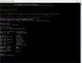
Connect the teensy to the WiiU.
Press power button on the WiiU.
Then connect the teensy to the PC and run the INFO command.
Last edited by Leeful,
oh interesting. I thought that teensy would be able to power the NAND through the 3.3v channel on the teensy board. In that case, I guess the 3.3v teensy mod isn't really necessary then? I have already done it anways, just saying.
*EDIT* Just found this on the NANDway page:
*EDIT* Just found this on the NANDway page:
- Vcc: Teensy 3.3V regulator cannot power the NANDs on the PS3. The drain of the motherboard summed by the other peripherals draw too much current (~1.8A). The NANDs can be powered from external 3.3V power supply like ATX power supply (the orange 3.3V line of the ATX main connector).
Last edited by Brenex,
Not sure on this. I know the TSOP chip runs at 3.3v so I thought that the teensy also needed to be running at 3.3v. Even if it is not powering the chip itself. Better to be safe than sorry. Anyone else any info/thoughts on this?oh interesting. I thought that teensy would be able to power the NAND through the 3.3v channel on the teensy board. In that case, I guess the 3.3v teensy mod isn't really necessary then? I have already done it anways, just saying.
I also tried to power the chip using an old PC ATX poer suppy but I could not get the teensy to recognise the chip. Everything shared the same ground and the 3.3v was correct but I just could not get it to work. mabe the wrong VCC connection point on the wiiU motherboard?
--------------------- MERGED ---------------------------
Sorry, I got the procedure wrong for booting the WiiU with the teensy. It should be:
Connect the teensy to the WiiU.
Press power button on the WiiU.
Then connect the teensy to the PC and run the INFO command.

Not sure on this. I know the TSOP chip runs at 3.3v so I thought that the teensy also needed to be running at 3.3v. Even if it is not powering the chip itself. Better to be safe than sorry. Anyone else any info/thoughts on this?
I also tried to power the chip using an old PC ATX poer suppy but I could not get the teensy to recognise the chip. Everything shared the same ground and the 3.3v was correct but I just could not get it to work. mabe the wrong VCC connection point on the wiiU motherboard?
--------------------- MERGED ---------------------------
Sorry, I got the procedure wrong for booting the WiiU with the teensy. It should be:
Connect the teensy to the WiiU.
Press power button on the WiiU.
Then connect the teensy to the PC and run the INFO command.
The connection you showed me above is direct to the Vcc so if that's the one you used (R210) it goes directly to Vcc. I will try your method above to power it up tomorrow and see if I can get the NANDway info command to read the NAND.
Dumping now
Attachments
Great to see you have made some progress with this.
On another note I've been trying to decrypt the nand dumps and this is what I've found that works.:
Code:To decrypt the image: openssl aes-128-cbc -d -nopad -K YOUR_KEY_FROM_OPT -iv 00000000000000000000000000000000 -in Input.img -out Decrypted.img
View attachment 77826 View attachment 77827Code:To re-encrypt the image: openssl enc -e -aes-128-cbc -nopad -K YOUR_KEY_FROM_OPT -iv 00000000000000000000000000000000 -in Decrypted.img -out RE-Encrypted.img
To make it more easy to get the OTP keys I've attatched a python script to extract the need keys for each nand. Just run it in the same folder as your otp.bin
Although this might not help the current situation it may be useful to someone in the future.
I decrypted my NAND hard dump using the above method. I edited the file to fix the incorrect default_title_id in HxDen. I then took that and reencrypted it using the openssl enc command. The bin it creates is not recognized by nandBinCheck unfortunately
Last edited by Brenex,
Oh well, it didn't work. After writing back a rednand SLC bin after having run it through nandBinFix and BinCheck using vwrite with no issues, now my Wii U just boots up to the Wii U screen and stays there permanently. No more error message. I only flashed back the SLC.

My Teensy 2.0 ++ that I ordered doesn't match up to the pics that @Leeful posted a few pages back. I had an extra Wii U and a full nand dump so I wanted to figure out the unbrick process. I have no idea where to solder the cables to the board. For example, on the teensy that I have there are no points that start with "A".
Solder points posted by Leeful:


 I already ordered the mcp1825_sot223 to solder to my teensy 2.0++ but the rest of the points don't match up. Here's what I have:

Solder points posted by Leeful:
Last edited by Kafluke,
Where do these diagrams come from? I have a shitty soldering iron and lifted two solder points from the board. Are there any alternative solder points?@Tommy084 Great to see someone else can confirm the eMMC dumping works. Could you let me know the make and model of the SD Card reader you used so that I can add it to the 'Working card readers list' in the OP. cheers.
When did you make your Rednand? Before or after you installed CBHC?
If it was before you installed CBHC writing back just the eMMC (MLC.img) backup from the rednand wont help because the modified VC game CBHC uses will not be on there.
On the other hand if the rednand backup was created after you installed CBHC it might work if it was only the modified VC game that caused the brick.
If the modified system.xml is the cause of the brick, writing back just the eMMC wont help because system.xml is on the TSOP nand and that needs to be dumped with a teensy.
Thats why the best bet to recover from a brick is to restore both the eMMC and the TSOP nands.
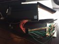
I still have not got around to soldering up the TSOP yet but if you want to try it out before me here are some pics I made that I was gonna post when I did it:
View attachment 77322 View attachment 77323 View attachment 77324 View attachment 77325
I'm not sure if the 3.3v needs to be connected to the WiiU at all yet(or where to put it. some say TP163 is the 3.3v supply to the nand but here Crediar says that is not 3.3v).
I was going to just power up the wiiU with the eMMC clock jumper disconnected so that it is in the same state that allows the eMMC to be dumped.
If that does not work the TSOP will have to be powered with the WiiU switched off with its own 3.3v power supply from either the Teensy (might not be enough) or from another power suppy.
On the Teensy side the Teensy needs to be converted to 3.3v and you will need NANDway.py here and you would program your teensy with the NANDway_DualNANDEdition.hex.
I wish I could try it myself but still I'm waiting for a new magnifying lamp to do the soldering.
UPDATE: DO NOT USE THE DUAL NAND EDITION SETUP AS MENTIONED ABOVE, INSTEAD USE THE SIGNAL BOOSTER EDITION SETUP AS I COULD NOT GET CONSISTANT DUMPS USING DUAL NAND EDITION !!!
View attachment 81467
They were my own images. Which points did you loose from the board?Where do these diagrams come from? I have a shitty soldering iron and lifted two solder points from the board. Are there any alternative solder points?
Similar threads
- Replies
- 7
- Views
- 4K
- Replies
- 40
- Views
- 5K
-
- Article
- Replies
- 251
- Views
- 42K
- Replies
- 9
- Views
- 2K
Site & Scene News
New Hot Discussed
-
-
62K views
Nintendo Switch firmware 18.0.0 has been released
It's the first Nintendo Switch firmware update of 2024. Made available as of today is system software version 18.0.0, marking a new milestone. According to the patch... -
24K views
Atmosphere CFW for Switch updated to pre-release version 1.7.0, adds support for firmware 18.0.0
After a couple days of Nintendo releasing their 18.0.0 firmware update, @SciresM releases a brand new update to his Atmosphere NX custom firmware for the Nintendo...by ShadowOne333 107 -
20K views
Wii U and 3DS online services shutting down today, but Pretendo is here to save the day
Today, April 8th, 2024, at 4PM PT, marks the day in which Nintendo permanently ends support for both the 3DS and the Wii U online services, which include co-op play...by ShadowOne333 179 -
16K views
GBAtemp Exclusive Introducing tempBOT AI - your new virtual GBAtemp companion and aide (April Fools)
Hello, GBAtemp members! After a prolonged absence, I am delighted to announce my return and upgraded form to you today... Introducing tempBOT AI 🤖 As the embodiment... -
13K views
Pokemon fangame hosting website "Relic Castle" taken down by The Pokemon Company
Yet another casualty goes down in the never-ending battle of copyright enforcement, and this time, it hit a big website which was the host for many fangames based and...by ShadowOne333 66 -
13K views
The first retro emulator hits Apple's App Store, but you should probably avoid it
With Apple having recently updated their guidelines for the App Store, iOS users have been left to speculate on specific wording and whether retro emulators as we... -
13K views
MisterFPGA has been updated to include an official release for its Nintendo 64 core
The highly popular and accurate FPGA hardware, MisterFGPA, has received today a brand new update with a long-awaited feature, or rather, a new core for hardcore...by ShadowOne333 54 -
12K views
Delta emulator now available on the App Store for iOS
The time has finally come, and after many, many years (if not decades) of Apple users having to side load emulator apps into their iOS devices through unofficial...by ShadowOne333 95 -
10K views
"TMNT: The Hyperstone Heist" for the SEGA Genesis / Mega Drive gets a brand new DX romhack with new features
The romhacking community is always a source for new ways to play retro games, from completely new levels or stages, characters, quality of life improvements, to flat...by ShadowOne333 36 -
10K views
Anbernic announces RG35XX 2024 Edition retro handheld
Retro handheld manufacturer Anbernic is releasing a refreshed model of its RG35XX handheld line. This new model, named RG35XX 2024 Edition, features the same...
-
-
-
225 replies
Nintendo Switch firmware 18.0.0 has been released
It's the first Nintendo Switch firmware update of 2024. Made available as of today is system software version 18.0.0, marking a new milestone. According to the patch...by Chary -
179 replies
Wii U and 3DS online services shutting down today, but Pretendo is here to save the day
Today, April 8th, 2024, at 4PM PT, marks the day in which Nintendo permanently ends support for both the 3DS and the Wii U online services, which include co-op play...by ShadowOne333 -
169 replies
GBAtemp Exclusive Introducing tempBOT AI - your new virtual GBAtemp companion and aide (April Fools)
Hello, GBAtemp members! After a prolonged absence, I am delighted to announce my return and upgraded form to you today... Introducing tempBOT AI 🤖 As the embodiment...by tempBOT -
107 replies
Atmosphere CFW for Switch updated to pre-release version 1.7.0, adds support for firmware 18.0.0
After a couple days of Nintendo releasing their 18.0.0 firmware update, @SciresM releases a brand new update to his Atmosphere NX custom firmware for the Nintendo...by ShadowOne333 -
96 replies
The first retro emulator hits Apple's App Store, but you should probably avoid it
With Apple having recently updated their guidelines for the App Store, iOS users have been left to speculate on specific wording and whether retro emulators as we...by Scarlet -
95 replies
Delta emulator now available on the App Store for iOS
The time has finally come, and after many, many years (if not decades) of Apple users having to side load emulator apps into their iOS devices through unofficial...by ShadowOne333 -
67 replies
Nintendo Switch firmware update 18.0.1 has been released
A new Nintendo Switch firmware update is here. System software version 18.0.1 has been released. This update offers the typical stability features as all other...by Chary -
66 replies
Pokemon fangame hosting website "Relic Castle" taken down by The Pokemon Company
Yet another casualty goes down in the never-ending battle of copyright enforcement, and this time, it hit a big website which was the host for many fangames based and...by ShadowOne333 -
54 replies
MisterFPGA has been updated to include an official release for its Nintendo 64 core
The highly popular and accurate FPGA hardware, MisterFGPA, has received today a brand new update with a long-awaited feature, or rather, a new core for hardcore...by ShadowOne333 -
53 replies
Nintendo "Indie World" stream announced for April 17th, 2024
Nintendo has recently announced through their social media accounts that a new Indie World stream will be airing tomorrow, scheduled for April 17th, 2024 at 7 a.m. PT...by ShadowOne333
-
Popular threads in this forum
General chit-chat
-
 Xdqwerty
Loading…what are you looking at?
Xdqwerty
Loading…what are you looking at?
-
 @
AncientBoi:
And a part of my immediate family passed also. Sending my good suit to the cleaners for the funeral Saturday
@
AncientBoi:
And a part of my immediate family passed also. Sending my good suit to the cleaners for the funeral Saturday -
-
-
-
-
-
@
Xdqwerty:
@SylverReZ, may I ask you something? What are your favorite animes? (Aside of serial code lain)
-
-
@
Xdqwerty:
Mines are all the dragon ball animes. Im also enjoying Fullmetal alchemist and my hero academia+1
-
-
-
-
-
-
-
-
-
-
-
-
-
-
-
-


