Hi everyone. In first place I want to thank everyone who discovered the method for modding the AGB-001 screen, and the people who posted their results so other people can learn about their mistakes and their success.
I also want to share my experience with these mods, in case anyone is interested, or maybe it is helpfull for someone.
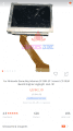
The first time I tried to do this mod, I had a 40 pin board. I ordered the screen and the adapter on Aliexpress. It was a white tabbed one. The result as everyone knows now, was washed out colors. I tried shorting every combination of signals I read on this thread (RECV, GND, COM, P2-VEE...), but the best thing I get was right colors but TERRIBLE ghosting (the image was retained for even minutes). After a lot of tries, trying to fix it, connecting and desconnecting the screen, soldering points, etc. I ended up breaking the ribbon cable of the screen

.
Reading that people had significantly more success with 32 pin motherboards, I found one on a local pawn shop. I ordered a second screen (white tabbed again), a 32 pin adapter, connected everything, tunned the potentiometer a bit, and voila, crystal clear image quality.
A few weeks ago I saw this post
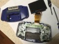
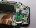
https://gbatemp.net/threads/40-pin-gba-with-white-tab-lcd-perfect-solution.448597/ so I decided to order a third screen, and try again the 40 pin motherboard. I just have to say, to anyone having trouble with a 40 pin motherboard, that this method absolutely fixes all the problems (washed colors, ghosting...). The result is as good as the 32 pin motherboard. Just remove R16, R17 and C33 for isolating P2-VEE on the board, short REVC to P2-VEE to take the unmodified RECV signal to the LCD, and remove C54 and Q3 to take the potentiometer directly to the LCD. A bit of tunning on the pot, and the result is PERFECT.
A lot of thanks to malheur and gaggi for sharing their discoverings.
But I didn't stop there. The 32 pin adapter I bought directly powers the lcd backlight trough the 5V rail. This gives too little brightness, so I tried soldering to the alternate points for increased brightness. But before doing that, I had to cut on the adapter the trace that goes from P1, to 5V, to prevent shorting the 5V rail to anywhere else. I read people saying that after soldering P1 to D1A, the console turns off. This is because the P1 on the ribbon adapter needs to be isolated from 5V rail first.
Soldering the cable, increased the brightness a little, but it was still too far from what the screen can do. So I connected the backlight to an external power supply, and increased the voltage very slowly. I saw that on 12V, the current was not too high (25mA), and the brightness was even a little higher than the AGS-101 on its highest setting.
The problem is the following: the AGB-001 doesn't have any 12V rail capable of supplying 25mA.
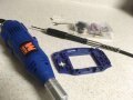
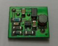
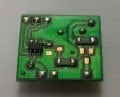
So I decided to use a DC/DC step up converter to elevate the 3.3V rail to 12V. I also implemented brightness level control trough the built-in GBA buttons. I made the following PCB:
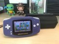
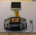
It uses a LMR64010 from Texas Instruments for elevating the voltage from 3.3V to 12V. This 12V can be directly taken to the LCD for the maximum brightness. In the other side of the PCB there is a a N-MOS transistor, for chopping the 12V rail, so the brightness is controlled trough PWM. The gate of the transistor is controlled by a Microchip PIC10LF322 microcontroller, which is connected to the SELECT, L and R buttons. This is the final assembly:
There are 6 brightness levels. The highest is a bit higher than AGS-101 on its high level. The lowest is far lower than AGS-101 on its low level. The other levels are intermediate.
By pressing SELECT + L the brightness is decreased and by pressing SELECT + R the brightness is increased. The microcontroller stores the setting on its memory, so everytime the console is powered up the brightness level is recalled. In the unlikely case a game uses the SELECT + L or SELECT + R combination, I implemented a lock function. By pressing the select button 3 seconds, the screen does a double blink, indicating that the brightness control has been locked. Pressing SELECT for 3 seconds again, unlocks the brightness control.
The following video shows how it works. The image quality and brightness control are far far away better on real life than on the video. This is the 40 pin one:
Sorry for my english, I am not a native english speaker.
Thanks for reading my post, and good luck to everyone modding their GBA. If anyone has questions, please feel free to ask.


")